Erector for J-Lay pipe laying system

a technology of laying system and stinger, which is applied in the direction of pipe laying and repair, pipe laying devices, pipe-laying vessels, etc., can solve the problems of inability to connect, damage beyond use, and the size, weight and cost of the stinger become prohibitive,

Inactive Publication Date: 2005-06-28
BAUGH BENTON F
View PDF30 Cites 60 Cited by
  • Summary
  • Abstract
  • Description
  • Claims
  • Application Information

AI Technical Summary

Benefits of technology

[0014]The object of this invention is to provide a tower which can be gimbaled to different angles while facilitating the welding of pipeline sections for laying pipelines on the ocean floor from a floating vessel.
[0015]A third object of this invention is to provide means for accurately aligning the ends of the pipelines for welding and laying.

Problems solved by technology

As water depths become greater; the size, weight, and cost of the stinger become prohibitive.
If it does not have horizontal tension, it will buckle as it is laid on the ocean floor and be damaged beyond use.
Bending the pipe around a stinger from a vertical tower makes the connections difficult and induces a high degree of stress in the pipeline.
Past J-Lay towers have had limited capability at best for changing the angle of the tower to facilitate laying the pipelines.
Rigidly installed, vertical towers engender a number of problems caused by an inability to respond in real time to the dynamic forces encountered during pipe laying operations.
Other deficiencies include the fact that they do not allow: 1) control of the bending stress and tension within the pipe string as it is deployed in an arc to the sea bed; 2) the laying vessel to weather vane or rotate about the pipe and thereby prevent torsional wind-up of the pipe string; and 3) precise control of the pipe lay envelope.
Further, current J-Lay tower designs omit any means for precise and accurate alignment of the pipe string and new pipe joints during the welding process.
Current stinger designs have a problem in that the internal geometry of the stinger is usually fixed at the diameter of the pipe string being deployed.
Additionally, such stingers only act as guide conduits for the pipe and do not stabilize, i.e., control the alignment of, the pipe as it emerges from the weld floor.
These flexible pipelines have found a place in the market due to the difficulties in the field installation of the lower capital cost steel tube pipeline.

Method used


Image

  • Erector for J-Lay pipe laying system
  • Erector for J-Lay pipe laying system
  • Erector for J-Lay pipe laying system

Examples


Embodiment Construction

[0043]Illustrative embodiments of the invention are described below. In the interest of clarity, not all features of an actual implementation are described in this specification. It will of course be appreciated that in the development of any such actual embodiment, numerous implementation-specific decisions must be made to achieve the developers' specific goals, such as compliance with system-related and business-related constraints, which will vary from one implementation to another. Moreover, it will be appreciated that such a development effort, even if complex and time-consuming, would be a routine undertaking for those of ordinary skill in the art having the benefit of this disclosure.

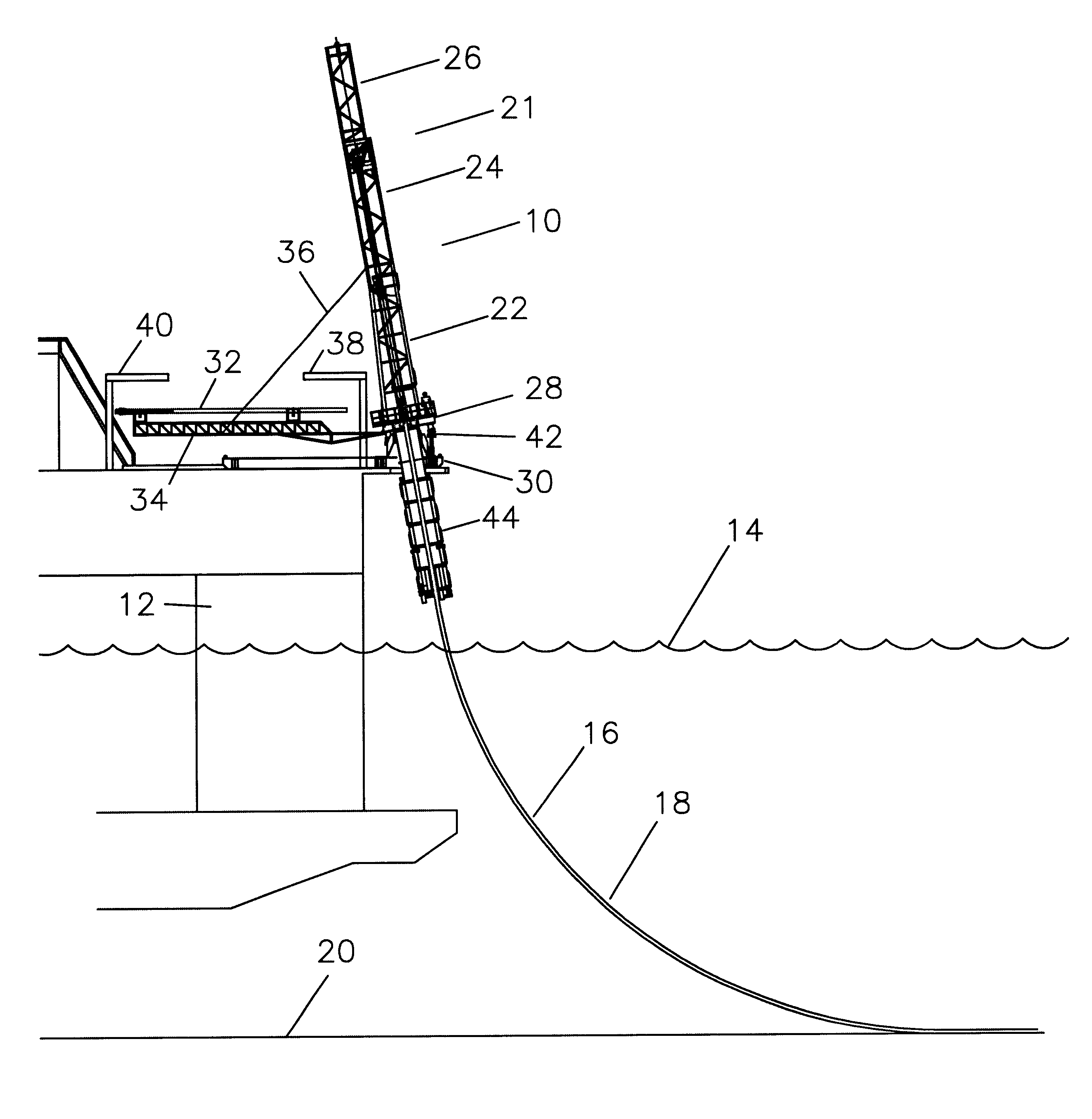
[0044]Referring now to FIG. 1, the j-lay tower 10 is shown on a floating vessel 12 in a body of water 14 with a pipeline 16 extending below the j-lay tower 10 around a bend 18 and onto the ocean floor 20. The j-lay tower 10 is shown with a mast 21 including a lower section 22, a middle section 24...


PUM


Abstract

A system for laying a pipeline from a floating vessel onto the ocean floor in relatively deep ocean water which provides an erector for raising new pipe sections to be added to a pipeline which is depending from the system, the pipe sections being raised into accurate alignment with the mast of the system although the mast is free to be gimbaled in any direction within two degrees of angular freedom.

Description

RELATED APPLICATIONS[0001]This application is a continuation of provisional application No. 60 / 083,964 filed May 1, 1998, incorporated herein by reference.BACKGROUND OF THE INVENTION[0002]1. Field of the Invention[0003]This invention relates generally to laying underwater pipelines in relatively deep water using a J-Lay method from a floating vessel and, more particularly, to installing underwater pipelines on the seabed and / or connecting the same to floating terminals at the surface.[0004]2. Description of the Related Art[0005]Subsea pipelines have most often been laid on the ocean floor by connection of welding on the deck of a barge, lowering off the back of the barge down a stinger, and then laying on the ocean floor. The curve down off the barge and then reverse curve onto the ocean floor gives a “S” bend in the pipeline during the lay process. The stinger allows the pipeline and its associated weight to be curved down toward the ocean floor without kinking or damaging the pipe...

Claims


Application Information

Patent Timeline
Patent Type & Authority Patents(United States)
IPC IPC(8): F16L1/12F16L1/235F16L1/20F16L1/19
CPCF16L1/19B63B35/03F16L1/235
Inventor BAUGH, BENTON F.
Owner BAUGH BENTON F
Why Eureka
Try Eureka