
Centrifuge comprising a blood bag system with an upper and lower outlet

a centrifuge and blood bag technology, applied in centrifugal force sediment separation, centrifugal force centrifuges, medical science, etc., can solve the problems of difficult plasma recovery, difficult separation of constituents, and more expensive manufacturing, so as to achieve high efficiency, function, and purity. the effect of high degr

Inactive Publication Date: 2005-06-28
ANDREAS HETTICH GMBH & CO KG
View PDF19 Cites 63 Cited by
  • Summary
  • Abstract
  • Description
  • Claims
  • Application Information

AI Technical Summary

Benefits of technology

[0007]One objective of this invention is therefore to further develop a centrifuge having a vertical blood bag system according to EP 0 350 495 B1 in such a way, so that blood bags that are normally commercially available could be utilized, without necessitating special adjustments of the bag. Another objective of the invention is to achieve recovery of the individual constituents with a substantially higher level of efficiency, functionality and with a higher degree of purity.

Problems solved by technology

One disadvantage of this is that recovery of plasma is difficult.
This vertical system, however, has again the disadvantage that the separation of the constituents is difficult because the extraction is achieved from the middle of a blood bag that is provided with an upper and a lower connection line.
This necessitates the insertion of a special blood bag which is thus more expensive to manufacture, and which can moreover be easily burst open.

Method used


Image

  • Centrifuge comprising a blood bag system with an upper and lower outlet
  • Centrifuge comprising a blood bag system with an upper and lower outlet
  • Centrifuge comprising a blood bag system with an upper and lower outlet

Examples


Embodiment Construction

[0041]The invention is described in the following description with reference to the figures, in which like numbers represent the same or similar elements.

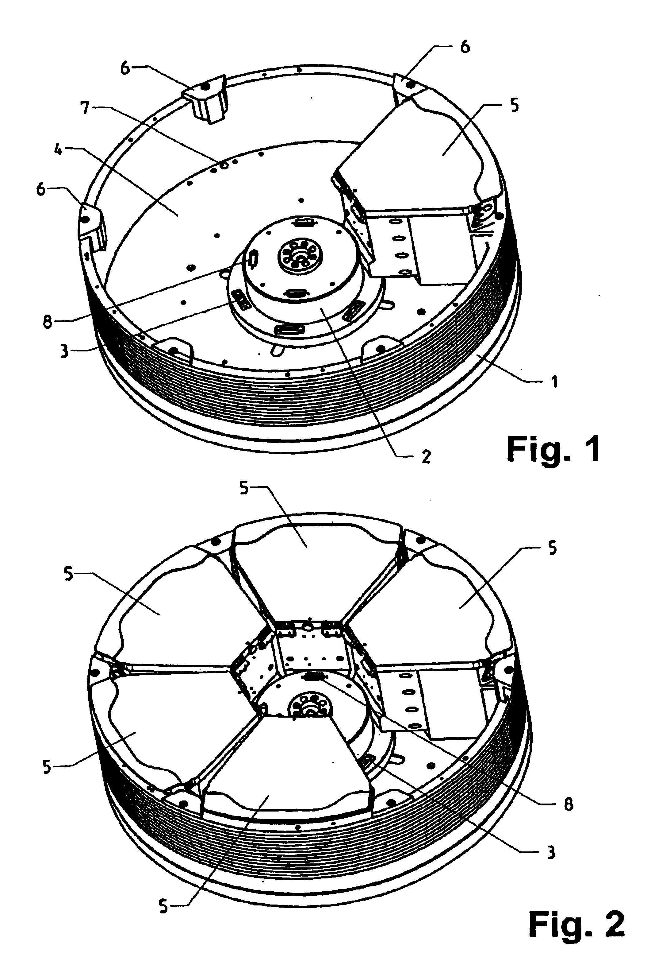
[0042]In accordance with FIG. 1, a hub 2, which is arranged in a rotor 1, is provided with a plurality of plug connections 3, 8. Through one of these plug connections can be supplied for instance energy for each of the cartridges 5 held therein, while air supplying operations can be conducted via the other plug connections 8. It is, however, also possible for example not to employ the plug connection 8 and supply air and electric energy only through the plug connections 3.

[0043]A plurality of cartridges 5 is arranged uniformly in the interior space 4 of the rotor, wherein these cartridges can be built-in between retaining pins 6 in a detachable manner on the circumference of the rotor. In another embodiment form, the cartridges 5 can be connected with the rotor in a fixed manner. Corresponding bores 7 are provided for this purpose ...


PUM

PropertyMeasurementUnit
Pressureaaaaaaaaaa
Widthaaaaaaaaaa
Translucencyaaaaaaaaaa

Abstract

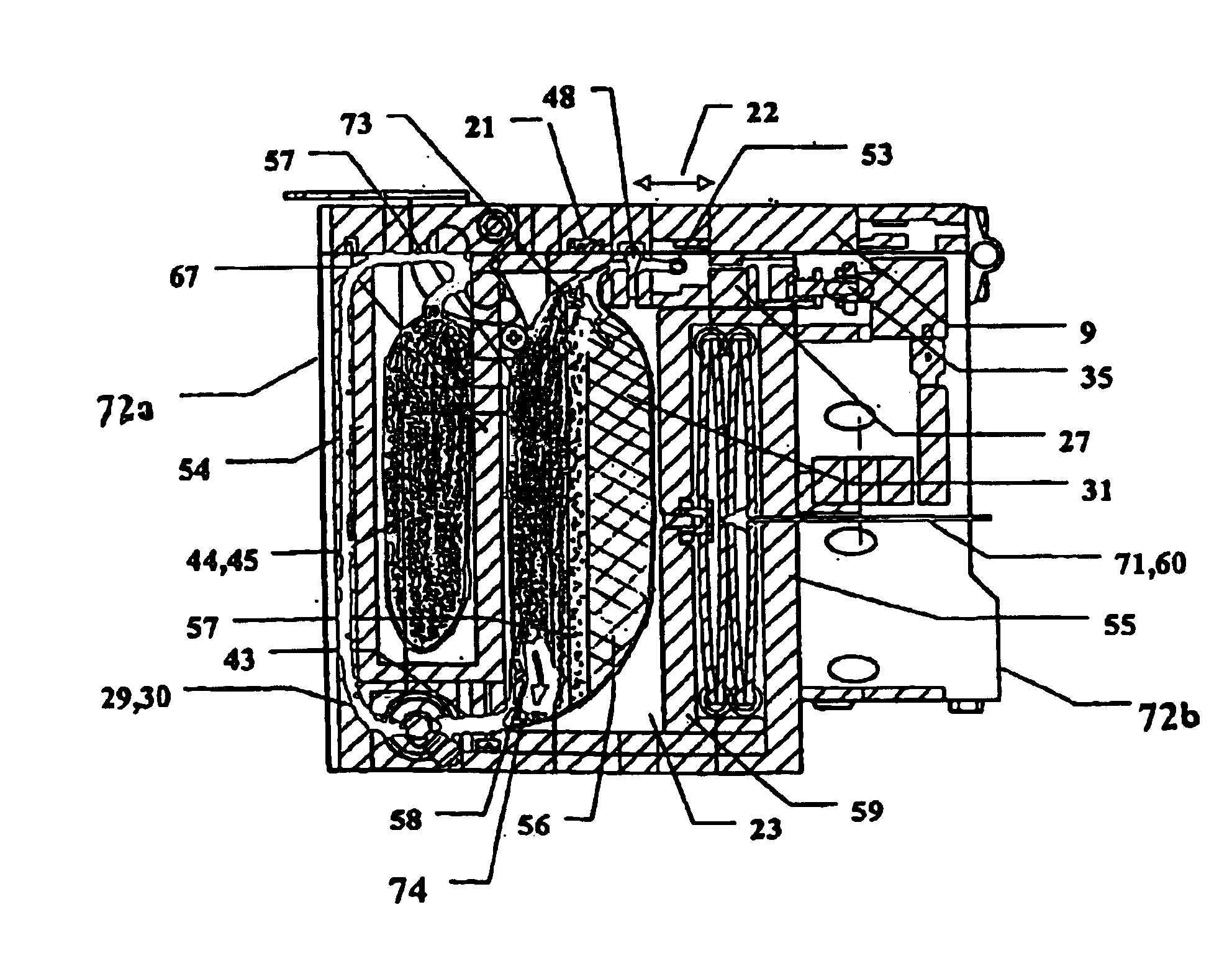
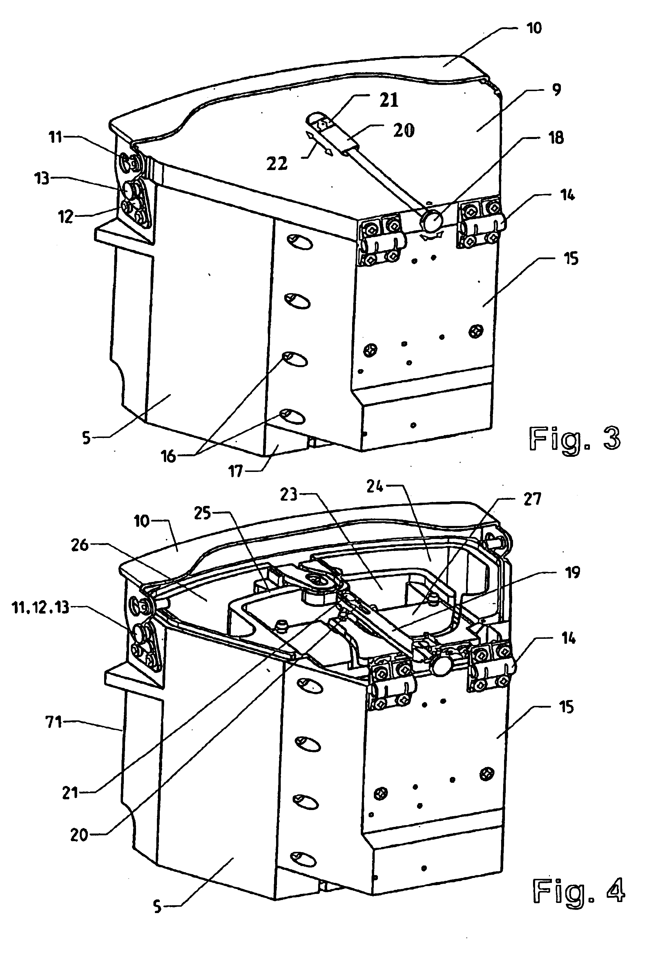
The invention relates to a centrifuge provided with a blood bag system having an upper and lower outlet for separation of blood constituents, containing a rotor which can be driven in a rotative manner about a hub, wherein at least one conventional whole blood bag equipped with an upper outlet and with a lower outlet can be positioned vertically in this blood bag, while the whole blood bag can be arranged on the rotor in such a way that one outlet of the whole blood bag is bent in a radial direction, and the opposite outlet of the whole blood bag is bent in the other radial direction, so that the entire whole blood bag and the outlets thereof adopt an approximately Z- or S-shaped form in its functional position. In this case it is preferred that the upper outlet of the whole blood bag lie radially toward the interior and the lower outlet of the whole blood bag lie radially toward the exterior of the whole blood bag. The whole blood bag is held in an insert, and the insert is in its turn held by an approximately sector-shaped cartridge, wherein a plurality of such cartridges is uniformly distributed by being arranged around the circumference of the rotor. One advantage of the centrifuge is that conventional blood bags can be used and recovery of individual blood constituents (plasma, erythrocytes, buffycoat) can be achieved with a significantly higher degree of efficiency and functionality, and with a high degree of purity.

Description

CROSS-REFERENCE TO RELATED APPLICATIONS[0001]This application is the U.S. National Stage of International Application No. PCT / EP01 / 14440, filed Dec. 8, 2001, entitled CENTRIFUGE COMPRISING A BLOOD BAG SYSTEM WITH AN UPPER AND LOWER OUTLET, and which is the International Stage of German Application No. 100 65 283.2, filed Dec. 29, 2000.BACKGROUND OF THE INVENTION[0002]1. Field of the Invention[0003]The invention relates to a centrifuge comprising a blood bag system with an upper and lower outlet for separation of blood constituents.[0004]2. Description of Related Art[0005]EP 0 026 417 B1, filed by the same applicant, discloses a centrifuge comprising a blood bag system, in which the blood bag is provided only with an upper outlet. One disadvantage of this is that recovery of plasma is difficult. In addition, that application involves a swing-out hanger attachment in which the phase boundaries between the individual constituents are formed at a vertical level during the operation of t...

Claims


Application Information

Patent Timeline
IPC IPC(8): B04B5/00B04B5/04
CPCB04B5/0428B04B2005/0435
Inventor EBERLE, GUNTER
Owner ANDREAS HETTICH GMBH & CO KG
Learn More