
Method and device for the electrolytic coating of a metal strip

a metal strip and electrolysis technology, applied in the field of electrolysis coating of metal strips, can solve the problems of affecting entail removal costs, and also involve raw materials, and achieve the effects of reducing the cost of removal, and improving the flow of electroly

Inactive Publication Date: 2005-06-28
CORUS TECH BV
View PDF2 Cites 3 Cited by
  • Summary
  • Abstract
  • Description
  • Claims
  • Application Information

AI Technical Summary

Benefits of technology

[0007]It is an object of the invention to provide a method with which the abovementioned drawbacks are eliminated or reduced. Another object of the invention is to be able to increase the running velocity of the strip, while the thickness of the layer which is deposited per unit length in a coating line can remain at least equal. Yet another object is to increase the efficiency of electrolysis on the strip. Yet another object is to provide a less expensive method for the electrolytic coating of a metal strip. Yet another object is to provide a method for electrolysis in which less waste material is produced.
[0008]One or more of these objects is achieved with a method of the type described in the first paragraph of this description in which the flow of the electrolyte is influenced by holding a body between the strip and the anode. In this way, the diffusion boundary layer in the electrolyte in the vicinity of the moving strip is influenced, with the result that the precipitation of anode material on the strip can proceed more efficiently and / or more homogeneously. A reduction in the thickness of the boundary layer, in particular, leads to an increased rate of deposition of material, so that the velocity at which the strip is moved through the coating line can be increased.

Problems solved by technology

However, the electrolyte breaks down at this non-soluble fraction of the anode, forming waste material.
On the one hand, this entails removal costs, and on the other hand raw material costs are also involved.

Method used


Image

  • Method and device for the electrolytic coating of a metal strip
  • Method and device for the electrolytic coating of a metal strip
  • Method and device for the electrolytic coating of a metal strip

Examples


Embodiment Construction

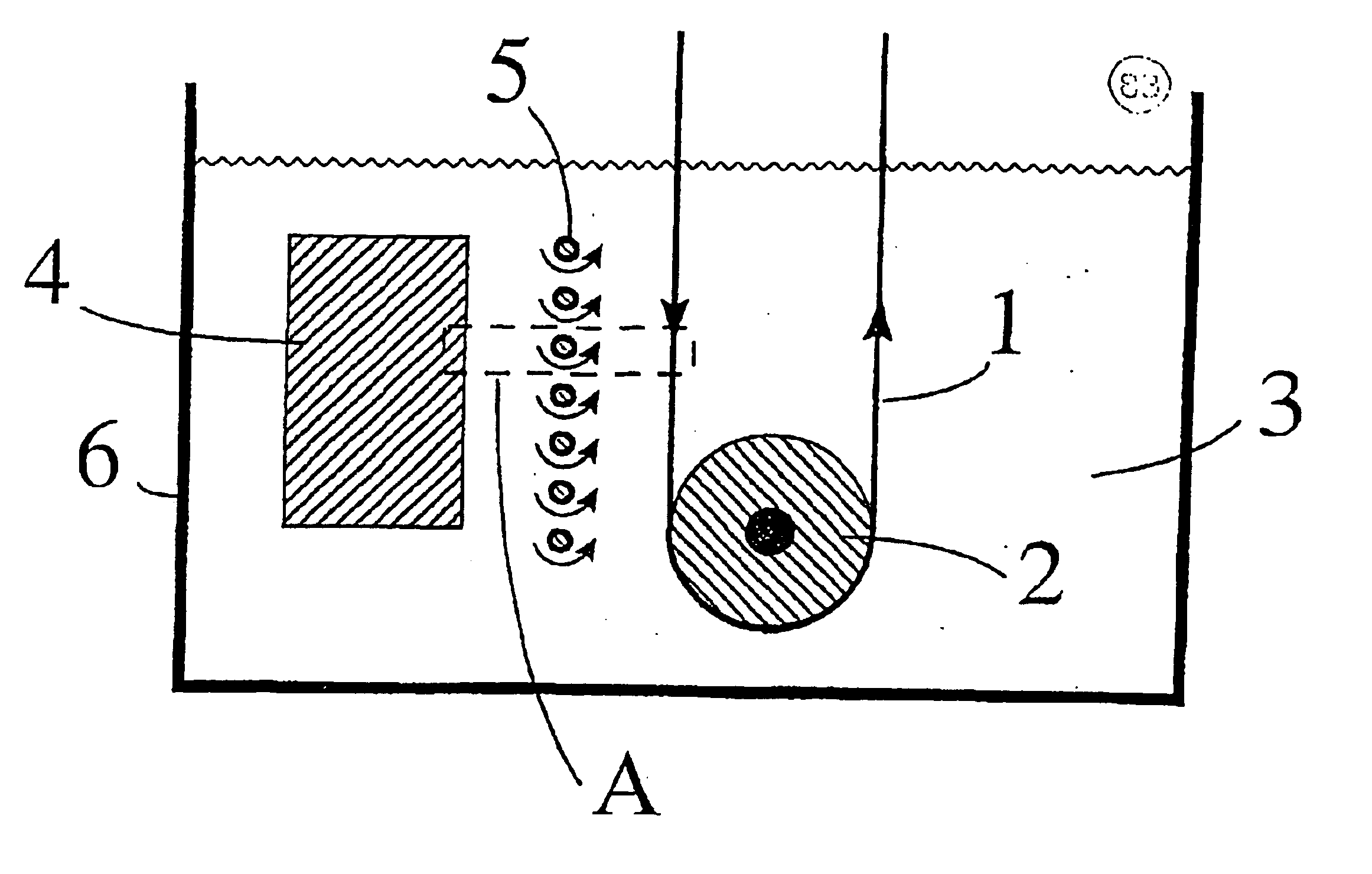
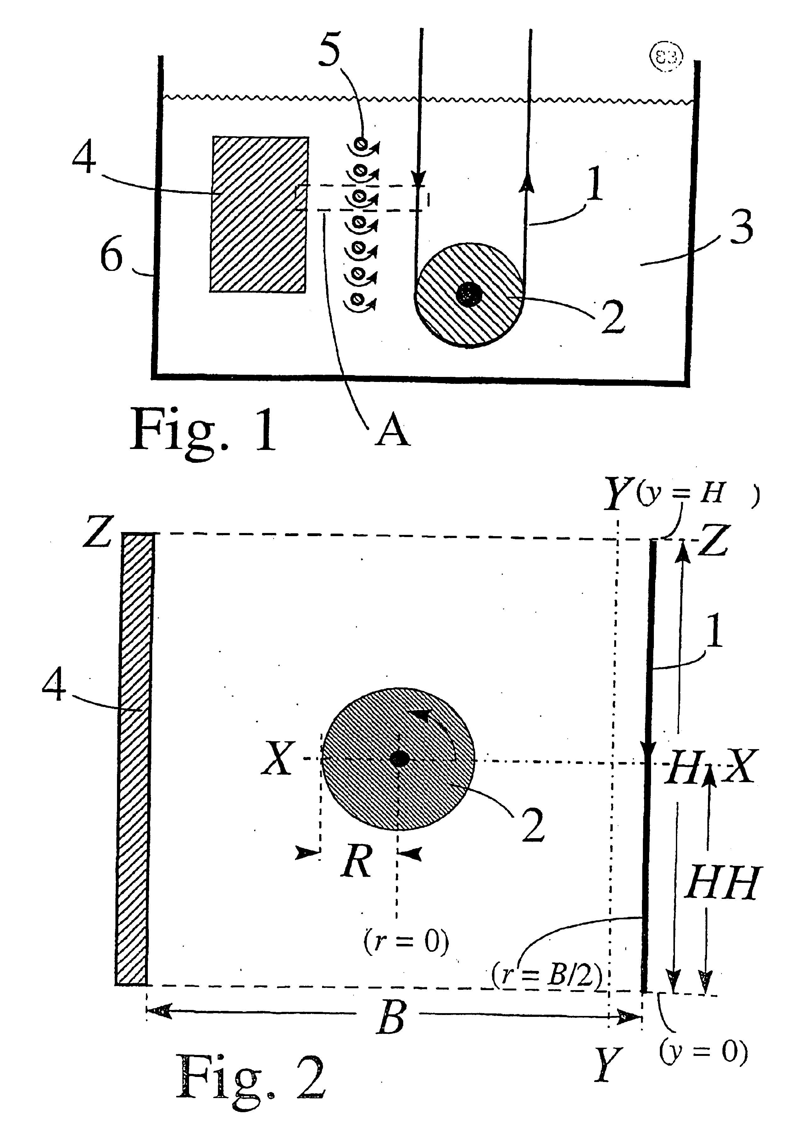
[0038]FIG. 1 shows a device for coating a metal strip with the aid of electrolysis, including a housing 6, a metal strip 1, an anode 4 and means for advancing the strip in its longitudinal direction, in the direction of the arrow, via a path at a certain distance from the anode, for example a conveyor roller 2. The housing 6 is filled with an electrolyte 3. Metal strip 1 is used as cathode. A potential difference is applied between metal strip 1 and anode 4, with the result that an electric current passes between the anode and the cathode, and electrolysis can take place. During electrolysis, material is deposited on the metal strip, so that it is coated with a layer.

[0039]According to the invention, the device also comprises a body 5 at least partially between the anode and the path of the metal strip. In the embodiment as shown in FIG. 1, there are a number of rod-like bodies 5 at equal distances from the metal strip. The rod-like bodies 5 can rotate in the direction of the arrows...


PUM

PropertyMeasurementUnit
Fractionaaaaaaaaaa
Frequencyaaaaaaaaaa
Frequencyaaaaaaaaaa

Abstract

Method for the electrolytic coating of a metal strip, in which the strip forms a cathode and is moved in its longitudinal direction relative to an anode, an electrolyte flowing at least between the strip and the anode, characterized in that the flow of the electrolyte is influenced by holding a body between the strip and the anode. A device for the electrolytic coating of a metal strip is also enclosed.

Description

FIELD OF THE INVENTION[0001]The invention relates firstly to a method for electrolytically coating of a metal strip, in which the strip forms a cathode and is moved in its longitudinal direction relative to an anode, an electrolyte flowing at least between the strip and the anode.BACKGROUND OF THE INVENTION[0002]A method of this type is generally known. In the known method, the distance between the metal strip and the anode is usually held at between 5 and 10 cm, while the strip which is to be coated, in the transverse direction in the vicinity of the anode, usually extends over a multiple (usually approximately 1 m) of this distance, with the result that a relatively narrow clearance is formed between the metal strip and the anode. A potential difference is applied between the anode and the cathode, leading to an electric current flowing through the electrolyte. In a method in which soluble anodes are used, the electric current leads to the dissolution of material, usually one or m...

Claims


Application Information

Patent Timeline
IPC IPC(8): C25D7/06C25D17/00C25D5/08C25D21/10C25D21/12
CPCC25D7/0685C25D5/08C25D7/06
Inventor VAN DER WEIJDE, DAMMES HANS
Owner CORUS TECH BV
Learn More