Hydrodynamic device

Inactive Publication Date: 2002-04-23
MANNESMANN SACHS AG
View PDF2 Cites 6 Cited by
  • Summary
  • Abstract
  • Description
  • Claims
  • Application Information

AI Technical Summary

Benefits of technology

The direction of the electric current flow in at least one area is not parallel to and is preferably substantially orthogonal to the direction of the magnetic field so that the interaction between the magnetic field and the electric current flow may be utilized with high efficiency in the hydrodynamic device according to the present invention.
The arrangement of the direction of the magnetic field non-parallel to and preferably substantially orthogonal to the work fluid flow direction in the at least one area also facilitates a high efficiency in influencing the flow characteristic of the work fluid. Further, the direction of the electric current flow in the at least one area is not parallel to and is preferably orthogonal to a direction of work fluid flow in the area.
High efficiency in the generation and transmission of torques may also be achieved in that at least one of the vane wheels has a plurality of vanes following one another in the circumferential direction.
Further, it is preferably provided in the hydrodynamic device according to the present invention that at least one of the vane wheels has an outer vane wheel element and an inner vane wheel element. The presence of the inner and outer vane wheel elements is preferably made use of, according to the present invention, so that the electric device for generating an electric current flow through the work fluid is arranged for generating an electrical potential difference between the outer vane wheel element and the inner vane wheel element of the at least one of the vane wheels. Accordingly, existing subassemblies or components in a vane wheel may be used additionally to form the potential difference, thereby obviating the need to add separate structural component parts or subassemblies for affecting the work fluid flow.
As mentioned above, the at least one vane wheel of the hydrodynamic device according to the present invention may comprise at least one impeller wheel and at least one turbine wheel when the hydrodynamic device comprises a torque converter or coupling. If the hydrodynamic device is also to perform the function of efficient torque conversion, it is advantageous when the at least one vane wheel of the hydrodynamic device according to the invention further comprises at least one stator wheel.
To minimize electrical losses for efficiently influencing the flow behavior of the work fluid, the work fluid comprises a specific resistance in the range of 10.sup.-7 m to 100 m.

Problems solved by technology

The construction of this known hydrodynamic torque converter is relatively complicated because it requires a throttle element that is displaceable even when the fluid pressure in the interior of the converter is relatively high and it requires control lines for the throttle element.
Further, since this known device requires an additional component which is mechanically displaceable during operation must be provided, i.e., the throttle element, the risk of malfunction, for example, when the throttle element jams as a result of vibrations, is increased over a torque converter without the throttle element.
The acceleration of the work fluid for strengthening the fluid-dynamic coupling cannot be achieved with the mechanically displaceable throttle element known from the prior art.

Method used


Image

  • Hydrodynamic device
  • Hydrodynamic device
  • Hydrodynamic device

Examples


Embodiment Construction

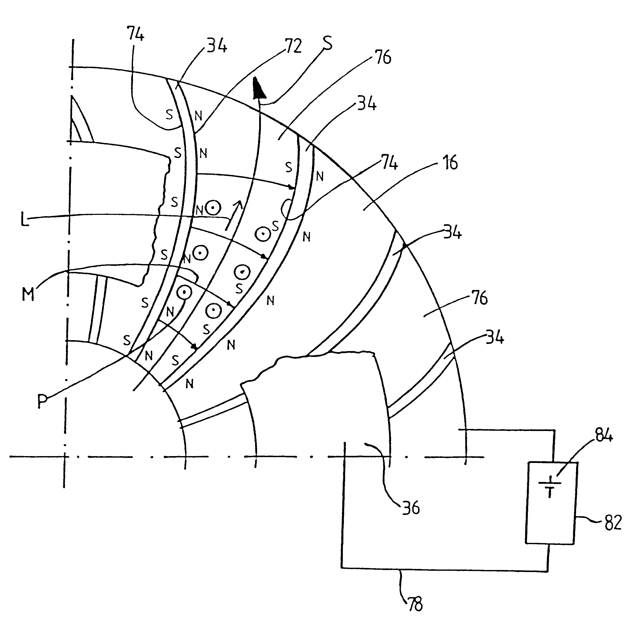
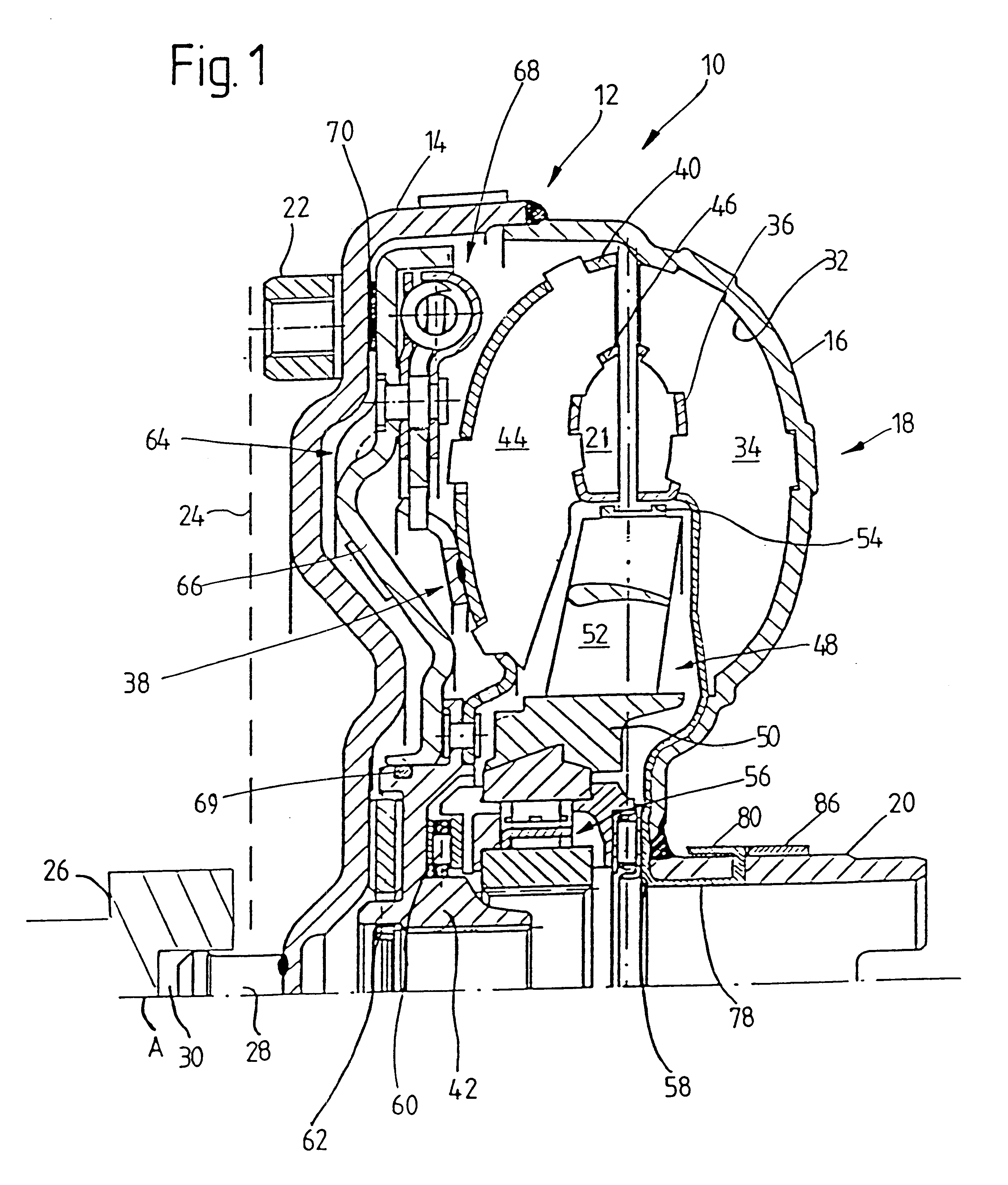
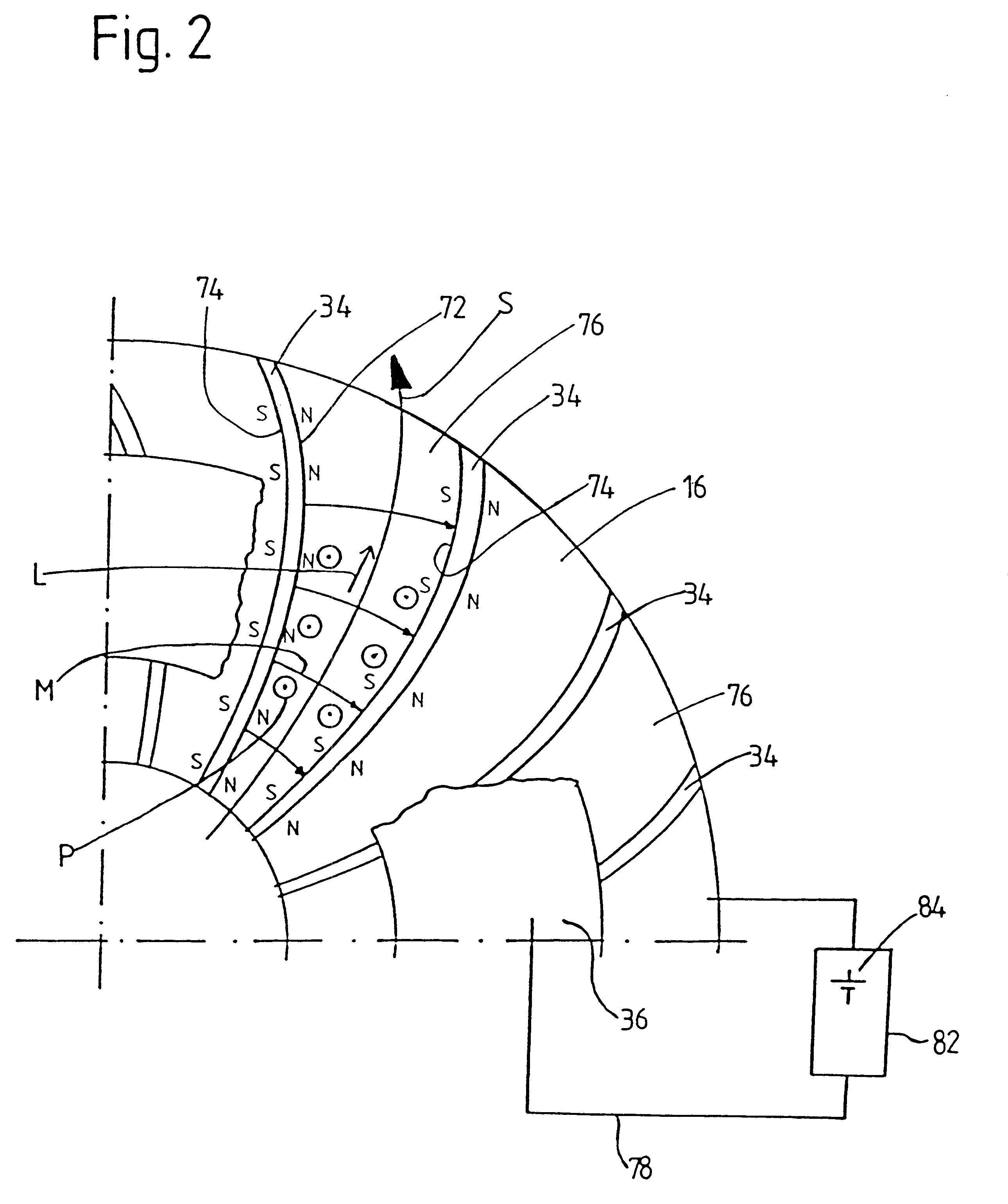
FIGS. 1 and 2 show a hydrodynamic device according to an embodiment of the present invention in the form of a hydrodynamic torque converter 10. The hydrodynamic torque converter 10 comprises a housing 12 with a housing cover 14 and an outer impeller wheel shell 16 of an impeller wheel 18. A radial inner side of the outer impeller wheel shell 16 is fixedly connected with an impeller wheel hub 20, for example, by welding. In a manner known per se, the impeller wheel hub 20 is arranged for driving a fluid pump through which fluid is conducted into an interior 21 of the torque converter 10. A radial outer area of the housing cover 14 has a plurality of nut-like coupling elements 22 which are fixedly connected to a drive shaft 26 via a connection arrangement 24. The drive shaft is rotatable about an axis of rotation A and the connection arrangement 24 is fixed with respect to rotation relative to the drive shaft 26. The connection arrangement 24 may be formed, for example, as a flexible ...


PUM


Abstract

A hydrodynamic device comprises at least one and preferably two vane wheels in a housing cover which are rotatable with respect to one another about an axis of rotation (A) and a work fluid arranged in the housing cover which can be driven to movement by the at least one vane wheel. The work fluid is electrically conductive and a magnetic device is provided for generating a magnetic field in the area of the work fluid circulation. Further, a electric device is provided for generating an electric current flow through the work fluid.

Description

1. Field of the InventionThe present invention is directed to a hydrodynamic device comprising at least one vane wheel arranged in a housing cover and rotatable about an axis of rotation and a work fluid in the housing cover which can be driven to movement by the at least one vane wheel.2. Description of the Related ArtA hydrodynamic device in the form of a hydrodynamic torque converter provided with a throttle element which is displaceable by the application of pressure for changing the converter characteristic is known from German reference DE 197 36 297 A1. The throttle element is selectively displaceable between an advanced position in which a throttle projection of the throttle element is engaged in the fluid circulation in the region of the impeller wheel and a retracted position in which there is essentially no such engagement. When the throttle projection is advanced into the fluid circulation, the fluid circulation is impeded so that the fluid-dynamic coupling between the i...

Claims


Application Information

Patent Timeline
IPC IPC(8): F16H45/02F16H45/00F16H61/38F16H61/50
CPCF16H61/50F16H45/02
Inventor SUDAU, JORG
Owner MANNESMANN SACHS AG
Why Eureka
Try Eureka