Integration of titanium and titanium nitride layers

a technology of titanium nitride and titanium nitride, which is applied in the direction of coatings, chemical vapor deposition coatings, electric discharge tubes, etc., can solve the problems of large amount of ongoing effort, reliability problems, and many traditional deposition processes that have difficulty in filling sub-micron structures

Inactive Publication Date: 2005-06-28
APPLIED MATERIALS INC
View PDF465 Cites 71 Cited by
  • Summary
  • Abstract
  • Description
  • Claims
  • Application Information

AI Technical Summary

Benefits of technology

[0010]Embodiments of the present invention generally relate to an apparatus and method of integration of titanium and titanium nitride layers. One embodiment includes providing one or more cycles of a first set of compounds, providing one or more cycles of a second set of compounds, and providing one or more cycles of a third set of compounds. One cycle of the first set of compounds includes introducing a titanium precursor and a reductant. One cycle of the second set of compounds includes introducing the titanium precursor and a silicon precursor. One cycle of the third set of compounds includes introducing the titanium precursor and a nitrogen precursor. Another embodiment i

Problems solved by technology

However, as the fringes of circuit technology are pressed, the shrinking dimensions of interconnects in VLSI and ULSI technology have placed additional demands on the processing capabilities.
Many traditional deposition processes have difficulty filling sub-micron structures where the aspect ratio exceeds 4:1.
Therefore, there is a great amount of ongoing effort being

Method used


Image

  • Integration of titanium and titanium nitride layers
  • Integration of titanium and titanium nitride layers
  • Integration of titanium and titanium nitride layers

Examples


Embodiment Construction

Formation of a TiSix and / or a TiSixNy Film

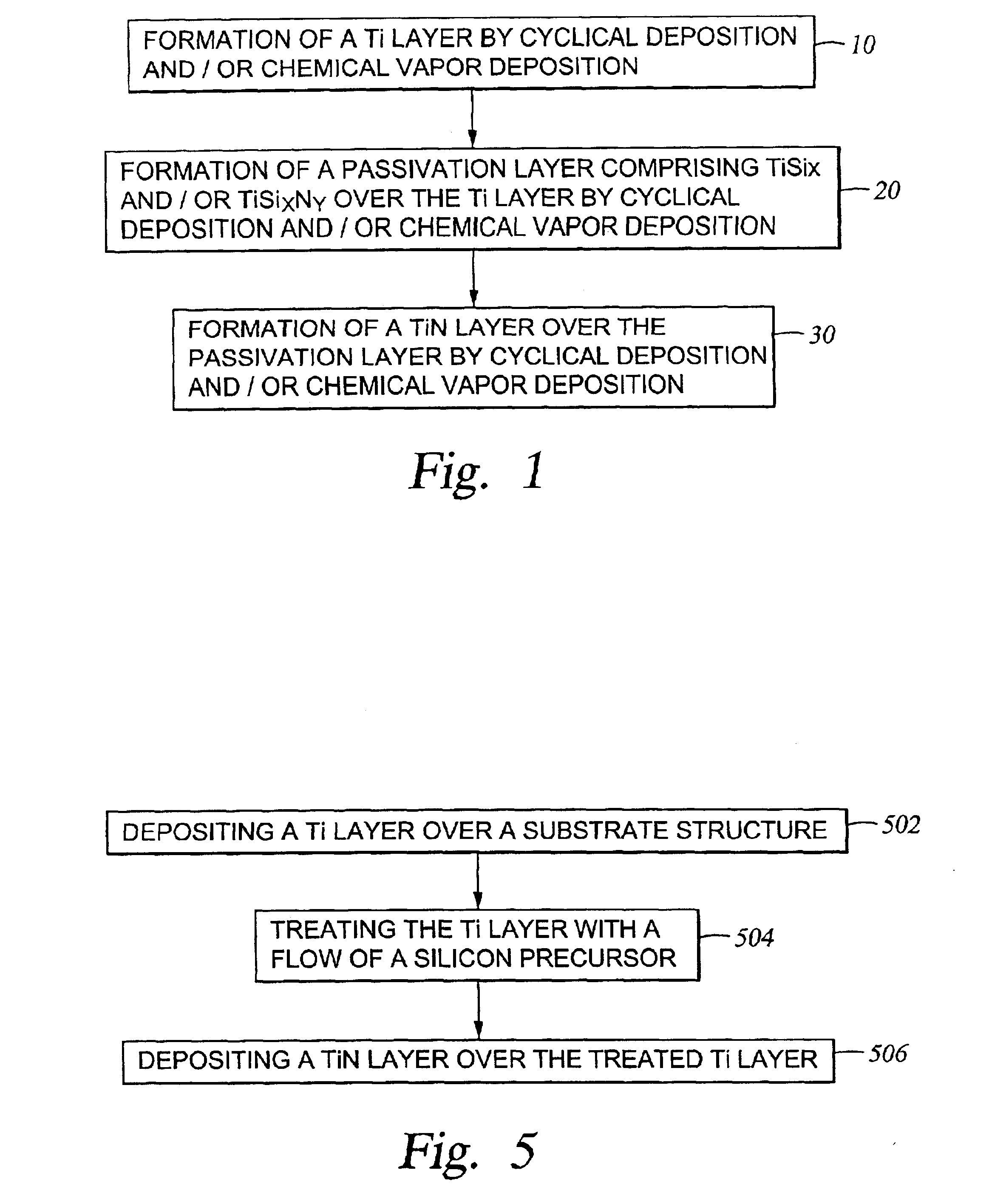
[0024]FIG. 1 is a flow chart illustrating one embodiment of a process of integrating a titanium (Ti) layer and a titanium nitride (TiN) layer by forming a titanium silicide (TiSix) layer and / or a titanium silicon nitride (TiSixNy) layer between the Ti layer and the TiN layer. In step 10, a Ti layer may be formed over a substrate structure by cyclical deposition, chemical vapor deposition, or a combined mode of cyclical deposition and chemical vapor deposition. In step 20, a passivation layer comprising titanium silicide and / or titanium silicon nitride may be formed over the Ti layer by cyclical deposition, chemical vapor deposition, or a combined mode of cyclical deposition and chemical vapor deposition. In step 30, a TiN layer may be formed over the passivation layer by cyclical deposition, chemical vapor deposition, or a combined mode of cyclical deposition and chemical vapor deposition.

[0025]Not wishing to be bound by theory, it is believ...


PUM

PropertyMeasurementUnit
Temperatureaaaaaaaaaa
Flow rateaaaaaaaaaa

Abstract

Embodiments of the present invention generally relate to an apparatus and method of integration of titanium and titanium nitride layers. One embodiment includes providing one or more cycles of a first set of compounds, providing one or more cycles of a second set of compounds, and providing one or more cycles of a third set of compounds. One cycle of the first set of compounds includes introducing a titanium precursor and a reductant. One cycle of the second set of compounds includes introducing the titanium precursor and a silicon precursor. One cycle of the third set of compounds includes introducing the titanium precursor and a nitrogen precursor. Another embodiment includes depositing a titanium layer utilizing titanium halide. Then, a passivation layer is deposited over the titanium layer utilizing titanium halide. The passivation layer may comprise titanium silicide, titanium silicon nitride, and combinations thereof. Then, a titanium nitride layer is deposited over the passivation layer utilizing titanium halide. Still another embodiment comprises depositing a titanium layer over a surface of a substrate. Then, the titanium layer is treated with a soak with a silicon precursor at a substrate temperature of about 550° C. or less to form a treated titanium layer. Then, a titanium nitride layer is deposited over the treated titanium layer.

Description

CROSS-REFERENCE TO RELATED APPLICATIONS[0001]This application claims benefit of U.S. provisional patent application Ser. No. 60 / 352,191, filed Jan. 26, 2002, which is herein incorporated by reference.BACKGROUND OF THE INVENTION[0002]1. Field of the Invention[0003]Embodiments of the present invention generally relate to an apparatus and method of integration of titanium and titanium nitride layers.[0004]2. Description of the Related Art[0005]Reliably producing sub-micron and smaller features is one of the key technologies for the next generation of very large scale integration (VLSI) and ultra large scale integration (ULSI) of semiconductor devices. However, as the fringes of circuit technology are pressed, the shrinking dimensions of interconnects in VLSI and ULSI technology have placed additional demands on the processing capabilities. The multilevel interconnects that lie at the heart of this technology require precise processing of high aspect ratio features, such as vias and oth...

Claims


Application Information

Patent Timeline
IPC IPC(8): C23C16/06C23C16/448C23C16/452C23C16/42C23C16/50C23C16/515C23C16/34C23C16/455H01J37/32H01L21/285H01L21/02H01L21/70H01L21/768C23C16/44H01L21/312
CPCC23C16/06H01L21/76856C23C16/42C23C16/452C23C16/45529C23C16/45531C23C16/45542C23C16/45565C23C16/5096C23C16/515C23C16/54H01J37/32082H01J37/3244H01L21/28556H01L21/28562H01L21/76843H01L21/76846H01L21/76855C23C16/34H01L21/28568H01L21/3122H01L21/3127H01L21/0228H01L21/02271H01L21/02153
Inventor YANG, MICHAEL X.ITOH, TOSHIOXI, MING
Owner APPLIED MATERIALS INC
Why Eureka
Try Eureka