Ion source

a technology of ion sources and cathode spots, which is applied in the field of ion sources, can solve the problems of cathode spots, their performance can decrease over the life of ion sources, and difficulty in establishing plasma

Inactive Publication Date: 2005-02-01
SAINTECH
View PDF4 Cites 155 Cited by
  • Summary
  • Abstract
  • Description
  • Claims
  • Application Information

AI Technical Summary

Problems solved by technology

The resultant high background pressure within the interelectrode space creates electrical instability leading to the generation of cathode spots within the ion source and extending to the extremities of the vacuum environment.
A further problem with present ion sources is that their performance can decrease over the life of the ion source.
Symptoms include difficulty in establishing the plasma and a reduced stability of the plasma.
The reduced electron flux into the ionization region firstly creates instability in the performance of the ion source and, secondly, causes an imbalance in the change neutrality of the resultant ion beam.

Method used


Image

  • Ion source
  • Ion source
  • Ion source

Examples


Embodiment Construction

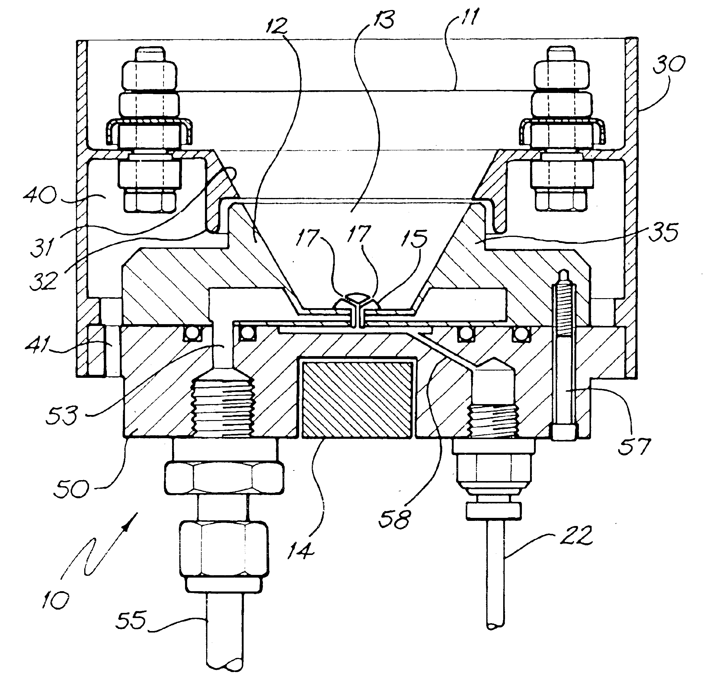
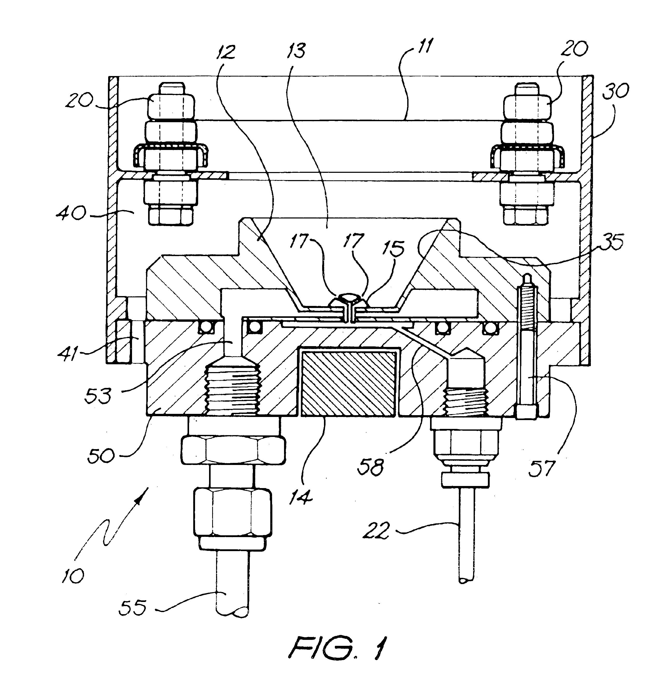
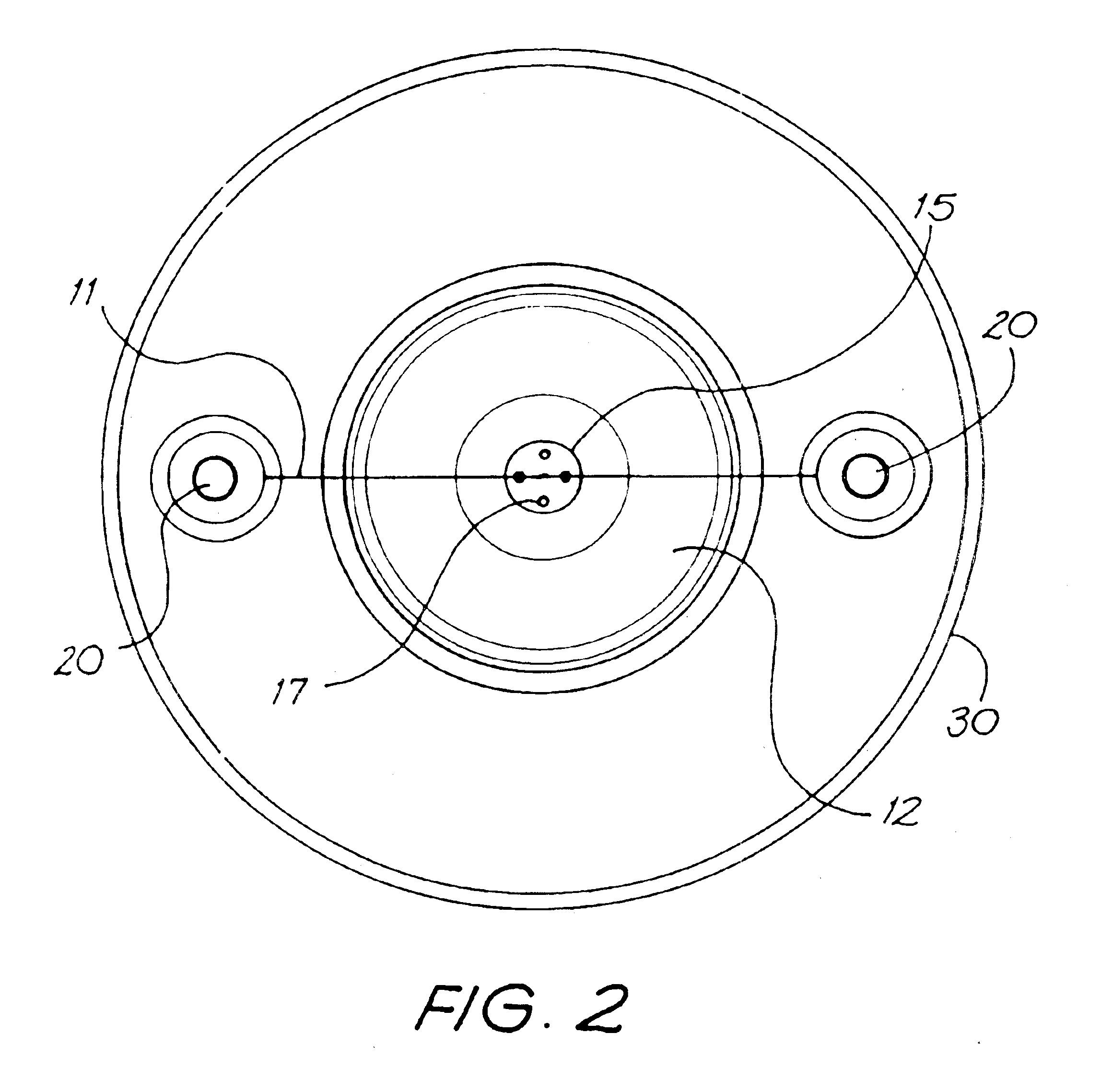
FIGS. 1 and 2 show an ion source generally at 10 having a cathode wire 11 and an anode 12. The anode 12 has an inner surface 35 sloping outwards in the direction of the cathode. Between the cathode 11 and the anode 12 is an ionization region 13. The cathode wire 11 is suspended above the anode by two mounting pins 20 that are held by, and in electric isolation from a shield plate 30. The shield plate 30 substantially surrounds the anode, cathode and ionization region by extending from a point lower than the anode 12 to a point above the cathode 11 and is preferably maintained at earth potential to shield the anode and the cathode from external fields.

A magnet 14 is disposed outside the ionization region 13 but adjacent the anode 12. The magnet 14 creates a magnetic field, the longitudinal axis of which is aligned with the axis of the anode 12. The magnet may be a permanent magnet or an electromagnet. Preferably the magnet is a high flux rare earth magnet such as a NdFeB magnet. As a...


PUM


Abstract

An ion source 10 for producing a beam of ions from a plasma is disclosed. A plasma is created at the center of an anode 12 by collisions between energetic electrons and molecules of an ionizable gas. The electrons are sourced from a cathode filament 11 and are accelerated to the anode 12 by an applied electric potential. A projection of the anode and a magnetic field having an axis aligned with the axis of the anode act together to concentrate the flow of electrons to the center of the anode 12. The ionizable gas is introduced into an ionization region 13 of the ion source 10 at the point of concentrated electron flow. Ions created in the ionization region are expelled from the ion source as an ion beam centred on the axis of the magnetic field. The surfaces of the anode are coated with an electrically conductive non-oxidising layer of Titanium Nitride to prevent a build up of an insulating layer on the anode.

Description

BACKGROUND OF THE INVENTIONThis invention relates to ion sources for producing an ion beam. The invention was developed through use with end-Hall effect ion sources and is, at times, described with particular reference thereto. It will be apparent to the skilled reader however, that the scope of the invention will encompass other types of ion sources.Ion sources had their origins in space propulsion but more recently have found use in more industrial processes such as Ion Assisted Deposition (IAD) of thin film coatings. In an IAD process, an ion beam from an ion source is directed onto a target substrate to cause densification of the coating material as it is deposited. The process occurs within an evacuated chamber of pressure of the order 10−2 Pa.In a typical ion source, electrons are drawn from a cathode filament toward an anode through an ionizable gas. Collisions between the gas molecules and energetic electrons create a source of positive ions by inducing a plasma. In one type...

Claims


Application Information

Patent Timeline
Patent Type & Authority Patents(United States)
IPC IPC(8): H01J49/10H01J49/00H01J49/12H01J27/02H01J27/14
CPCH01J27/14H01J27/02
Inventor SAINTY, WAYNE GREGORY
Owner SAINTECH
Why Eureka
Try Eureka