Apparatus for converting a fluid into at least two gasses through electrolysis

a technology of fluid and gas, applied in the field of apparatus for converting fluid into at least two gasses, can solve the problems of increasing the complexity of what on the surface, requiring a large amount of electrical power, and inefficient generation of the latter, and achieves low power input, low cost, and significant reduction of anode/cathode arcing.

Inactive Publication Date: 2005-05-10
SULLIVAN JOHN T
View PDF13 Cites 24 Cited by
  • Summary
  • Abstract
  • Description
  • Claims
  • Application Information

AI Technical Summary

Benefits of technology

[0009]It is an object of the present invention to provide an electrolysis apparatus which is extremely inexpensive to manufacture, significantly reduces anode / cathode arcing is relatively lightweight, and produces separate gasses which can be individually immediately utilized and / or stored and accomplish the latter at low power input and low overall total cost.
[0010]The primary object of the invention latter-stated is realized by an electrolysis apparatus which includes a novel encapsulation system for electrodes (anode or cathode) which allows oppositely charged electrodes to be placed into intimate contiguous relationship with each other to thereby increase ion conduction or flow or electron conduction or flow and correspondingly increase the generation of gasses. The encapsulation system is preferably a sheet of flexible material which is folded along one edge to completely encapsulate an electrode therein and remaining edges of the envelope are sealed to each other. A fluid delivery tube, which can also be an electrical conductor, has an end located in the electrode of the encapsulation envelope for introducing fluid therein, such as water with or without an additive electrolyte, and communicating generated gas bubbles to an exterior source of utilization or storage. A rod at an end of the electrode opposite the tube also has an end passed through the encapsulation envelope for conducting power to / through the electrode, and both the rod and the tube serve as supports for the encapsulate electrode in the overall apparatus / electrolyzer. The material of the encapsulating envelope is either substantially electrically conductive or substantially non-conductive. In one embodiment of the invention the encapsulation material is substantially impervious to gas bubbles but “porous” or conductive to electron flow and in a second embodiment the encapsulation material is substantially electro-chemically conductive to ion flow (Proton Exchange Membrane—PEM) and non-porous to gas bubbles. Therefore, when a plurality of the encapsulated electrodes and non-encapsulated electrodes of different polarities are placed in alternating side-by-side intimate contacting relationship to each other within a container or vessel containing fluid and like fluid is introduced into the encapsulation envelopes and the electrodes are appropriately energized, one of either ions / protons or electrons flow between the cathodes and anodes absent arcing therebetween while the generated gas bubbles are confined within each encapsulation envelope and container. The identical gas in each encapsulation envelope bubbles through the fluid therein and is directed to the source of utilization or storage by the aforementioned tubes while the gas is in the container, obviously differing from the gas in the encapsulation envelopes, is likewise collected by another tube and is delivered to a different source of utilization or storage. Thus, through the utilization of an encapsulating medium which can be substantially porous or non-porous, substantially electrically non-conductive or electrically conductive or electro-chemically conductive, highly efficient low cost fluid / liquid-to-gas electrolysis is provided by the present invention.

Problems solved by technology

This patent describes a conventional electrolysis cell as including two electrodes arranged within the cell which apply energy to the water to thereby produce hydrogen and oxygen, but the generation of the latter is said to be inefficient, requires a large amount of electrical power, and uses a chemical catalyst, such as a sodium hydroxide or potassium hydroxide.
Excessive heating and the tendency of hydrogen and oxygen bubbles to bunch around or on the electrodes which create electrical insulation are additional problems recognized in this patent.
The patent actually adds complexity to what on the surface is a simple chemical reaction which heretofore necessitated the utilization of complex apparatuses requiring the use of expensive materials, numerous parts, painstaking assembly (stacked and bolted components), excessive weight per gas generated, etc.
The patent also fails to address immediately separating the gasses, be they hydrogen and oxygen or otherwise, upon generation thereof in order to be individually immediately utilized as a power source for internal combustion engines, stoves, furnaces, or the like.
The PFA is designed to meet the fuel needs of up to 5 efficient fuel cell vehicles.” The hydrogen generated is extremely low and unmentioned is the high ratio of platform weight to volume of hydrogen generated and the high cost of any of these electrolysis units.

Method used


Image

  • Apparatus for converting a fluid into at least two gasses through electrolysis
  • Apparatus for converting a fluid into at least two gasses through electrolysis
  • Apparatus for converting a fluid into at least two gasses through electrolysis

Examples


Embodiment Construction

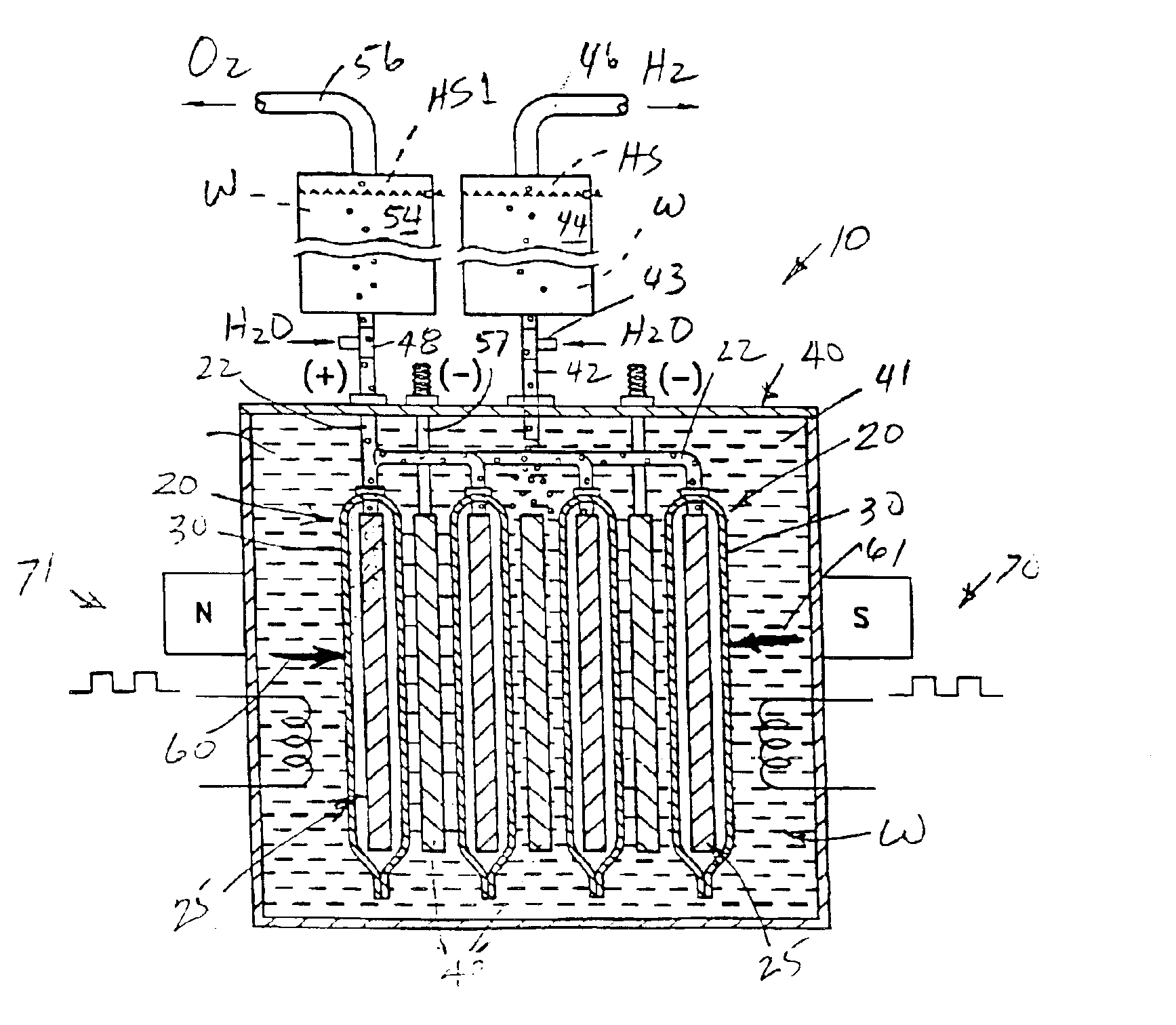
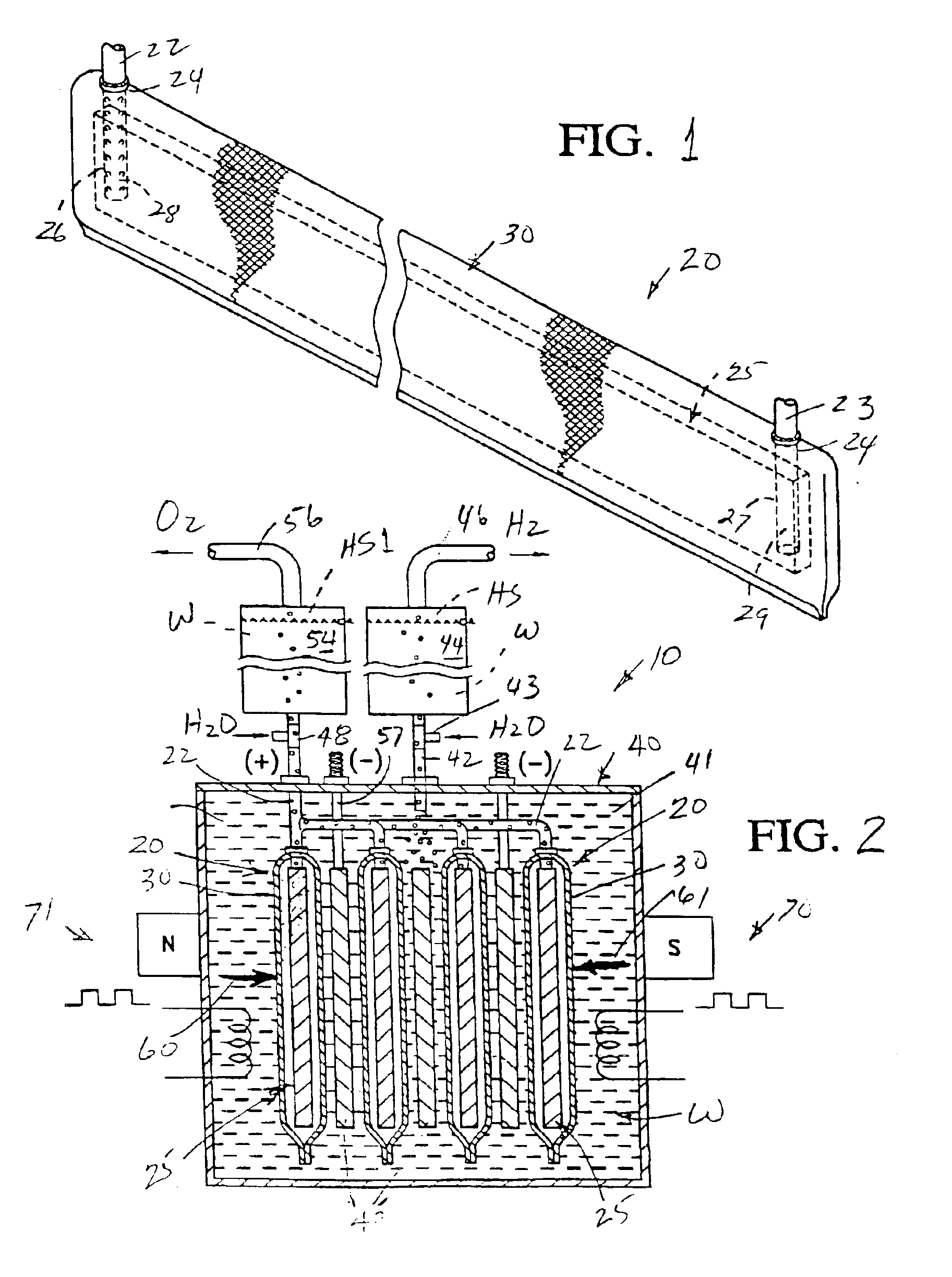
[0034]A novel liquid-to-gas electrolysis conversion system or apparatus for converting a fluid / liquid into at least two gasses, such as converting water into hydrogen and oxygen, through electrolysis is shown in FIG. 2 and is generally designated by the reference numeral 10.

[0035]A major aspect of the present invention involves the construction of a novel electrode encapsulation system 20 (FIG. 1) in the form of either an encapsulated anode or an encapsulated cathode, depending upon the manner in which current is connected to and flows therethrough.

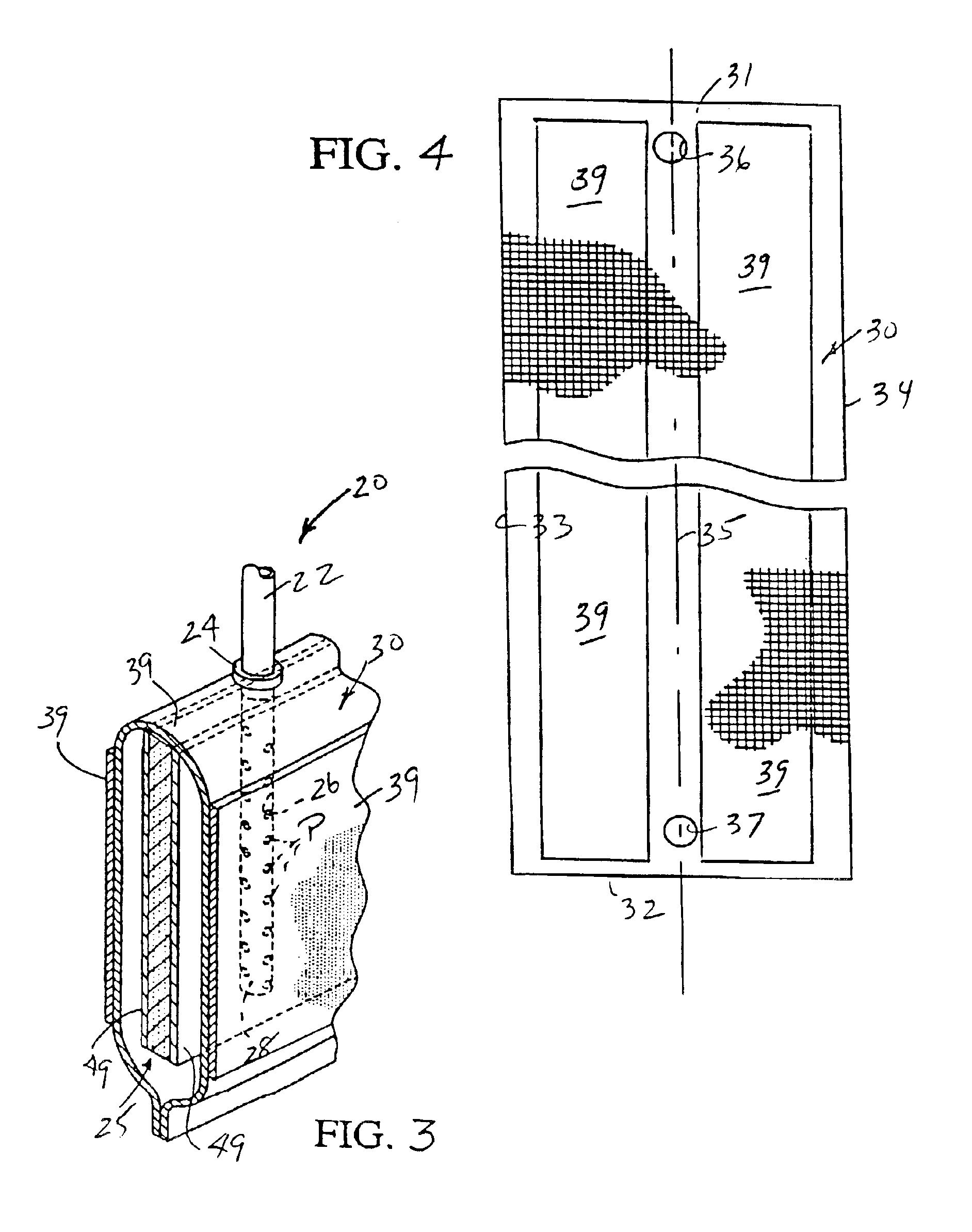
[0036]The electrode encapsulation system or encapsulated electrode 20 is defined by a porous electrode 25 (FIG. 3) and a substantially polygonal / rectangular sheet 30 (FIG. 4) of relatively flexible material.

[0037]The porous electrode 25 is preferably constructed from electrically conductive sintered stainless steel or sintered nickel, but if made of solid electrically conductive material, such as solid stainless steel, the same is prefera...


PUM

PropertyMeasurementUnit
electron conductionaaaaaaaaaa
metallicaaaaaaaaaa
flexibleaaaaaaaaaa

Abstract

An electrolysis conversion system for converting liquid to gas, such as water into hydrogen and oxygen, includes a housing in which are housed encapsulated and non-encapsulated electrodes in any one of side-by-side, rolled or folded relationship. The electrodes are immersed in an electrolyte, water or the like and are appropriately electrically connected to positive and negative sides of an energy source. The encapsulation material of the encapsulated electrodes can be substantially conductive or non-conductive to either ion flow or electron flow and either substantially non-porous or porous to gas bubbles with the option of utilizing spacers to prevent arcing and thereby generate hydrogen and oxygen from the water / electrolyte. The encapsulating media is either a folded flexible sheet heat sealed along three edges, two sheets heat sealed along four edges, a tube heat sealed along opposite axial edges or a coating dip-coated, electro-deposited, silk screen coated or similarly applied to the electrode which is preferably porous and can either be rigid or relatively bendable / flexible.

Description

BACKGROUND OF THE INVENTION[0001]The present invention is directed to an apparatus for converting a fluid into at least two gasses through electrolysis, and more specifically to an apparatus for producing hydrogen and oxygen from water with or without a catalyst. In lieu of utilizing water as the fluid, other fluids, additives and / or catalysts can be provided to generate gasses other than hydrogen and oxygen.[0002]1. Field of the Invention[0003]The field of the invention is an apparatus for converting a fluid into at least two gasses.[0004]2. Description of Related Art[0005]A conventional electrolysis cell for producing hydrogen and oxygen from water is disclosed in U.S. Pat. No. 6,126,794 issued on Oct. 3, 2000. This patent describes a conventional electrolysis cell as including two electrodes arranged within the cell which apply energy to the water to thereby produce hydrogen and oxygen, but the generation of the latter is said to be inefficient, requires a large amount of electri...

Claims


Application Information

Patent Timeline
Patent Type & Authority Patents(United States)
IPC IPC(8): C25B11/00C25B1/04C25B1/00C25B9/06C25B13/00C25B9/08C25B9/10C25B11/02C25B9/17C25B9/19C25B9/23
CPCC25B1/04C25B9/06C25B9/08C25B11/02C25B13/00C25B9/10Y02E60/366Y02E60/36C25B9/17C25B9/23C25B9/19
Inventor SULLIVAN, JOHN T.
Owner SULLIVAN JOHN T
Why Eureka
Try Eureka