Preloaded parabolic dish antenna and the method of making it

a parabolic dish and antenna technology, applied in the field of preloading parabolic dish antennas, can solve the problems of increasing the weight of structural members, requiring considerable welding or bolting, etc., and achieve the effects of improving the back-up structure, reducing the overall cost, and being light in weigh

Inactive Publication Date: 2005-06-28
TATA INSTITUTE OF FUNDAMENTAL RESEARCH
View PDF4 Cites 11 Cited by
  • Summary
  • Abstract
  • Description
  • Claims
  • Application Information

AI Technical Summary

Benefits of technology

[0003]The principal object of the present invention is to provide an improved back-up structure for parabolic dish antennas which is light in weight and has lower overall cost.

Problems solved by technology

The conventional design leads to increased weight of the structural members and also requires considerable amount of welding or bolting.
Also the required curvature of both the radial and circumferential members is made by rolling or bending in a suitable machine which is labour intensive.

Method used


Image

  • Preloaded parabolic dish antenna and the method of making it
  • Preloaded parabolic dish antenna and the method of making it
  • Preloaded parabolic dish antenna and the method of making it

Examples


Embodiment Construction

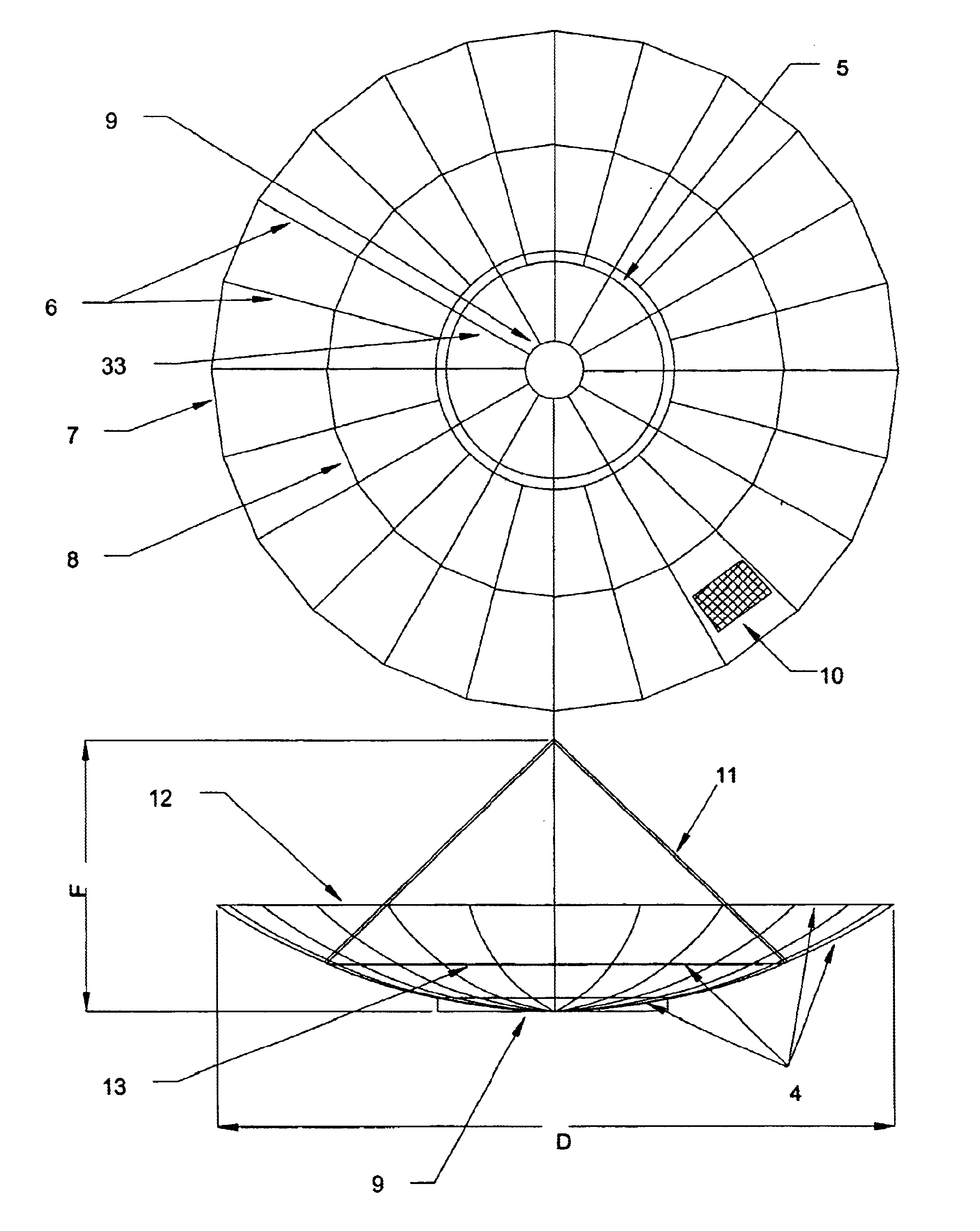
[0058]The required curvature of the elastically bent radial members can be made nearly the same as that of the parabolic curve of the dish antenna in a number of ways, for example (a) by means of fixing of the straight radial members at a suitable location at the central hub as well as inclination angle with respect to the plane of the central hub and then applying a force with a normal component at their tips for achieving the desired curvature and then connecting them rigidly to rim members forming a near circular (regular polygon) circumferntial ring; (b) by first prebending the radial members slightly to a curvature of relatively large radius and then fixing them at a suitable inclination angle and location at the central hub and then applying a force with a normal component at their tips for achieving the desired curvature; (c) by elastically bending the radial members firstly from the hub to an intermediate ring made of bracing members using suitable tensioning devices and the...


PUM


Abstract

The back-up structure of a parabolic dish antenna, which supports its reflecting surface, is formed in this invention by preloading its radial and circumferentially placed straight structural members and hence it is termed as preloaded parabolic dish antenna. Such a preloading results in considerable reduction in its weight and also to the effort involved in its assembly. The back-up structure of the preloaded parabolic dish antenna is made of a central hub, an assembly of a suitable number of elastically bent radial structural members connected rigidly to the central hub and to the same number of straight structural members which are connected to the tips of the radial members at the outer rim of the dish and also to straight bracing members placed circumferentially at intermediate locations, which are all tensioned to specified prestress values in the absence of wind loading. The outermost rim members placed at the periphery of the dish form the aperture of the dish. The backup structure of the preloaded parabolic dish antenna is given the parabolic shape by fixing the radial members at a suitable inclination angle and location at the hub and by applying an appropriate force with a normal component at their tips so as to bend the radial members elastically such that their curvature becomes approximately the same as that of the parabolic curve between the hub and the peripheral rim point. The invention incorporates a suitable rigid connection of the elastically bent radial members and other structural members in order to store sufficient initial elastic energy in the back-up structure of the dish for resisting gravitational and static and dynamic wind forces on the parabolic dish antenna for the survival wind condition at the antenna site. This configuration also reduces moment of the wind forces and torques on the mounting tower and gear drive system of the dish antenna. This invention is also applicable to structures of geometries other than that of the parabolic dishes. The method of constructing the preloaded parabolic dish and attaching reflector panels of lightweight is also disclosed.
The preloaded parabolic dish antennas are useful in microwave communication, satellite communication, radar, radio telescope and other similar applications for receiving and/or transmitting radio waves.

Description

CROSS REFERENCE TO RELATED APPLICATION[0001]This application is a national stage of PCT / IN01 / 00137 filed Jul. 30, 2001 and based upon INDIA 721 / MUM / 2000 filed Aug. 1, 2000 under the International Convention.FIELD OF INVENTION[0002]This invention relates to parabolic dish antennas used in microwave communication, satellite communication, radars, radio telescopes and in other applications. This invention also relates to the fabrication of such parabolic dish antennas. More particularly the invention relates to parabolic dish antennas having diameter in the range of about 5 m to 100 m.OBJECT OF THE INVENTION[0003]The principal object of the present invention is to provide an improved back-up structure for parabolic dish antennas which is light in weight and has lower overall cost.[0004]It is a further object of the invention to provide a method of fabrication of the back-up structure of parabolic dish antennas by preloading its structural members such that the assembly has reduced weig...

Claims


Application Information

Patent Timeline
Patent Type & Authority Patents(United States)
IPC IPC(8): H01Q15/14H01Q15/16
CPCH01Q1/005H01Q15/168H01Q15/147H01Q15/141
Inventor SWARUP, GOVINDTAPDE, SURESH CHANDRA
Owner TATA INSTITUTE OF FUNDAMENTAL RESEARCH
Why Eureka
Try Eureka