Switching power supply

a power supply and switch technology, applied in the direction of electric variable regulation, process and machine control, instruments, etc., can solve the problems of affecting the operation of the circuitry, voltage drop or heat evolution at the detection resistor, and the effect of chronological changes in capacitance, etc., to achieve the effect of reducing power consumption

Inactive Publication Date: 2005-06-28
SONY CORP
View PDF4 Cites 23 Cited by
  • Summary
  • Abstract
  • Description
  • Claims
  • Application Information

AI Technical Summary

Benefits of technology

[0016]It is therefore an object of the present invention to provide a switching power supply apparatus in which the standby time switching operation is performed intermittently, by simply adjusting the values of respective key devices, without appreciably changing the pre-existing circuit, to minimize the power consumption to achieve energy saving during the standby time, as well as to enable ordinary operations, such as constant voltage constant current operations or various protective functional operations, without being affected by the circuitry designed to perform the intermittent operations.

Problems solved by technology

Moreover, there is raised a problem of the effect of chronological changes in capacitance because a large capacitance is required and hence an electrolytic capacitor of good volume capacitance ratio is used.
In the case of a heavy load, the voltage drop or heat evolution at the detection resistor poses a problem.
However, the circuitry becomes complicated to raise the cost.
In startup, the photocoupler for verifying the load state experiences an output devoid state and hence the driving voltage is in shortage because certain time is needed until the secondary side output voltage is increased to a setting value.
Moreover, the photocoupler is on at all times during the normal operation, thus consuming redundant power, with the result that power saving during the operation is not achieved.

Method used


Image

  • Switching power supply
  • Switching power supply
  • Switching power supply

Examples


Embodiment Construction

[0022]Referring to the drawings, a present embodiment of the present invention is explained in detail.

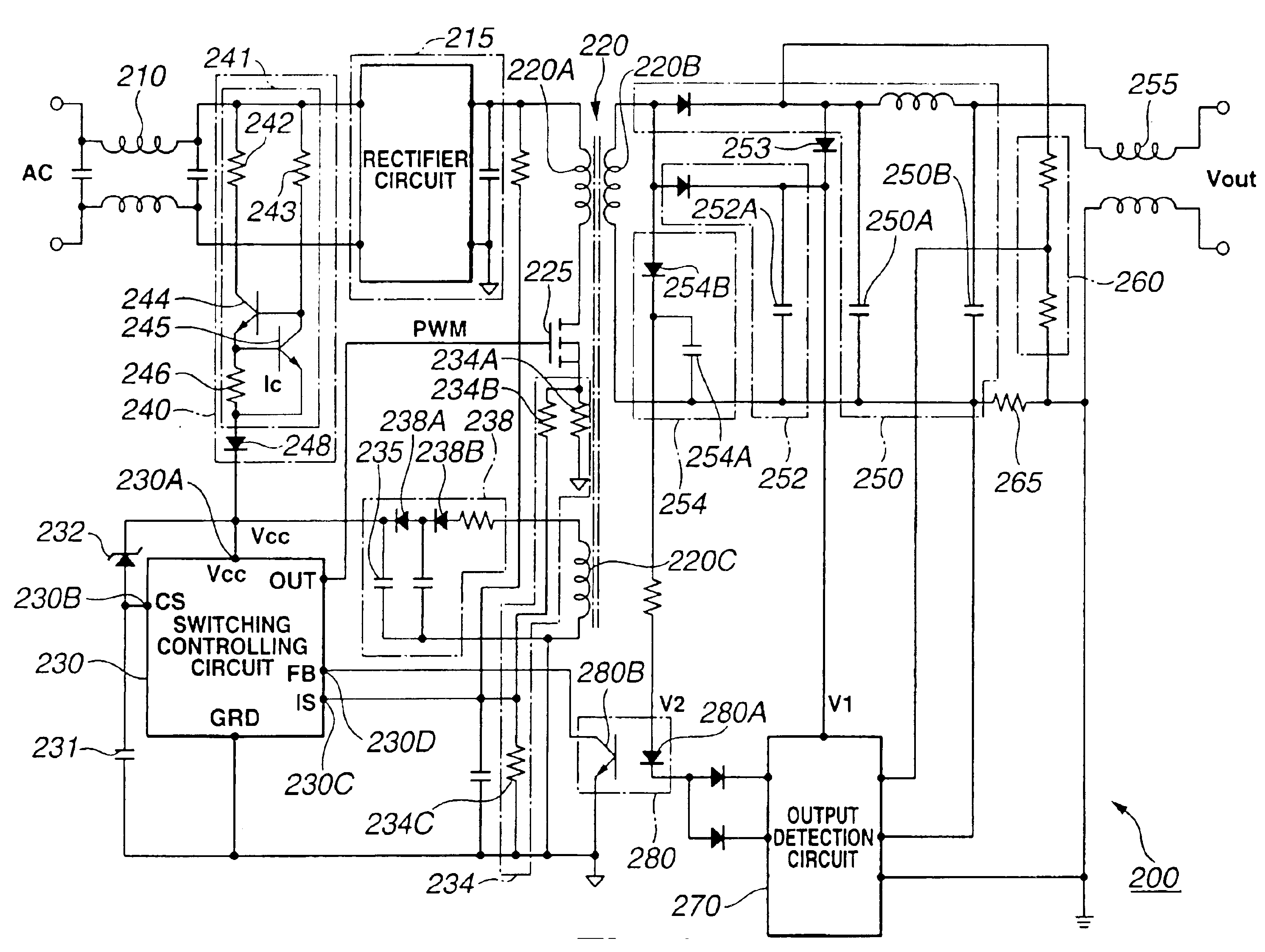
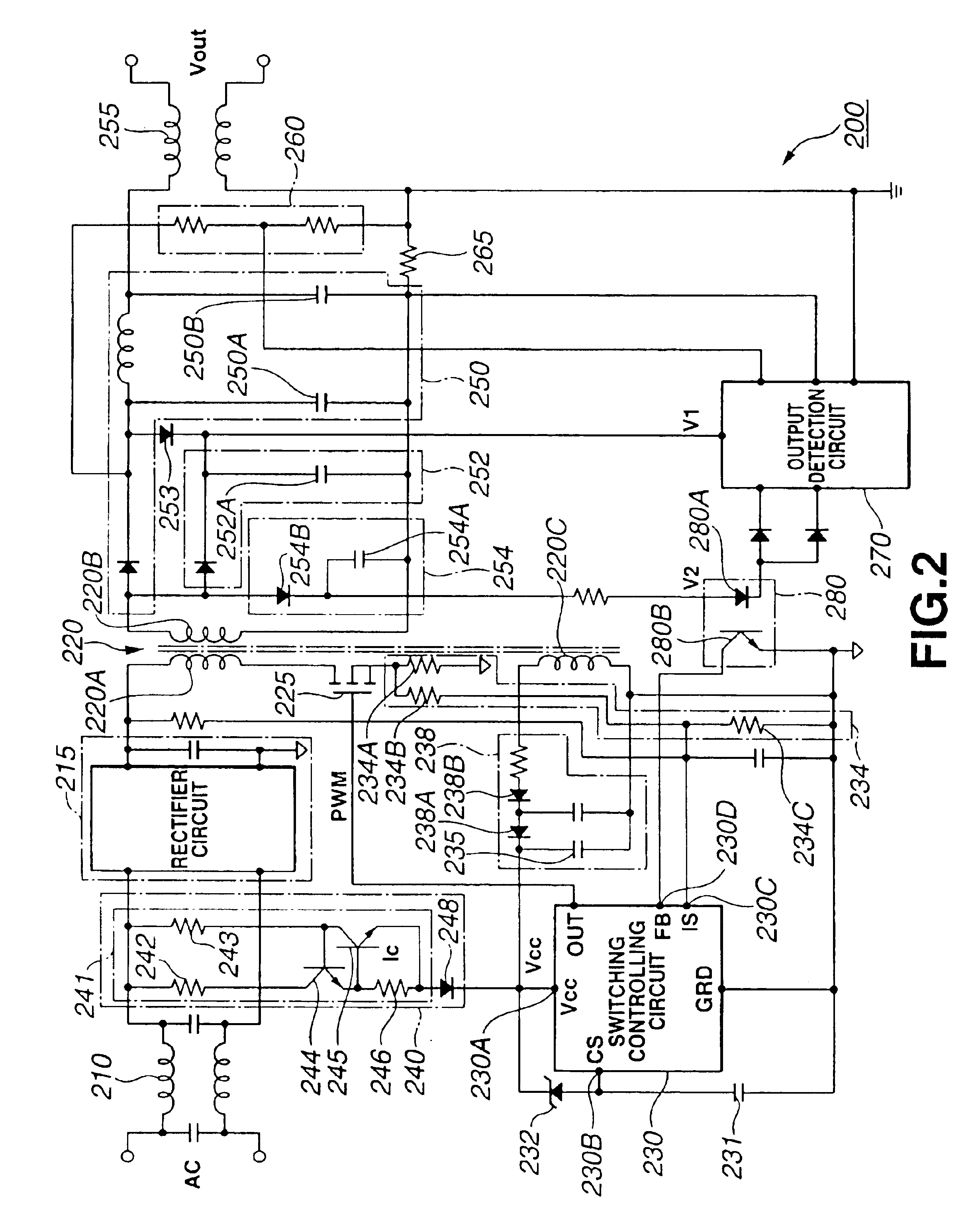
[0023]The present invention is applied to a switching power supply apparatus 200 having a structure shown for example in FIG. 2.

[0024]This switching power supply apparatus 200 includes a primary side rectifying smoothing circuit 215, for rectifying and smoothing the AC input supplied from the commercial power supply AC through an AC filter 210. To this primary side rectifying smoothing circuit 215 is connected the drain of a switching FET 225 through a primary winding 220A of a converter transformer 220.

[0025]There is also connected a switching controlling circuit 230 for PWM controlling the switching operation of the switching FET 225. The junction point of the AC filter 210 and the primary side rectifying smoothing circuit 215 is connected through a startup circuit 240 to a power supply terminal 230A of the switching controlling circuit 230.

[0026]The power supply terminal 230A of ...


PUM


Abstract

A switching power supply apparatus (200) for controlling the operation of a switching FET (225) adapted for switching a rectified smoothed output of a primary side rectifying smoothing circuit (215) by a switching controlling circuit (230) having a hysteresis low-voltage mistaken operation prohibiting circuit. An output of a ternary winding (220C) of a converter transformer is rectified and smoothed by a rectifying smoothing circuit (238) to drive the switching controlling circuit (230). An output voltage of the ternary winding (220C), varied in dependence upon the load state on the secondary side of a converter transformer (220) is set so as to be lower than a low voltage protective voltage in case the voltage is lower than a design load and so as to be higher than the low voltage protective voltage in case the voltage is higher than the design load, in order to carry out an intermittent operation during standby time. Thus, the switching operation during standby time may be carried out intermittently to minimize the power consumption to realize the energy saving during standby time, simply by adjusting the values of respective key devices, without appreciably changing the pre-existing circuitry.

Description

BACKGROUND OF THE INVENTION[0001]This invention relates to a switching power supply apparatus for controlling the switching operation of a switching element adapted for switching a rectified smoothed output of a primary side rectifying smoothing circuit by a switching controlling circuit having a hysteresis low-voltage mistaken operation preventative circuit.BACKGROUND ART[0002]Up to now, a switching power supply apparatus for switching a DC current, obtained on rectifying and smoothing the commercial AC current, at a high frequency on the order of, for example, 100 kHz, and for transforming the resulting current to a desired voltage by a transformer to a high efficiency, has been in use.[0003]As an output voltage controlling system in the above-described switching power supply apparatus, a pule width modulation (PWM) controlling system for controlling the duty ratio of the switching pulses responsive to changes in the output voltage, and a frequency (e.g., resonation) controlling s...

Claims


Application Information

Patent Timeline
Patent Type & Authority Patents(United States)
IPC IPC(8): H02M3/335H02M3/24H02M3/28
CPCH02M3/33523H02M3/33507H02M3/28
Inventor KONNO, AKIRA
Owner SONY CORP
Why Eureka
Try Eureka