This methodology has many problems.
The X.10 protocol itself, which uses signals transmitted from a controller over standard
AC power lines within the house to receivers that control electronic devices, is slow and unreliable.
This is too long for many applications, such as automated lighting, because humans—expecting an automated response—start to question whether the lights will come on at all after that amount of time.
Moreover, most receivers do not acknowledge to the controller that the command was received.
Therefore, if the command is not properly received, nothing gets controlled.
Some recent X.10 modules now include “2-Way
Transmitter Receivers” which acknowledge receiving commands, but the controllers for such modules are very expensive and the
acknowledgement is very slow.
Lastly, the X.10 protocol is very limited in its command set with only 16 defined commands.
There is the possibility of having more commands, but there's not a standard for this protocol, and these additional commands take a long time to send.
Other protocols using standard
AC power lines tend to be too slow and expensive.
Traditional sensors used to recognize the presence of people in a room are slow and too prone to false positives.
The problem with this approach is that either: (a) the sensitivity is set high enough to quickly detect people entering a room, in which case events such as the heat turning on or sudden
sunlight changes may also indicate to the sensor that someone has entered the room (a condition known as a “false positive”) or (b) the sensitivity of the sensor is turned down enough to prevent false positives, in which case the sensor takes too long to recognize people entering the room or it fails to recognize the presence of people in the room at all.
Further, these sensors have problems accurately determining if people are present when those people are not moving much or at all (e.g. reading or watching television).
This implies that each installation gets very little knowledge from previous installations and that there is very little reproducibility among homes.
Therefore, the programs tend to be limited in functionality.
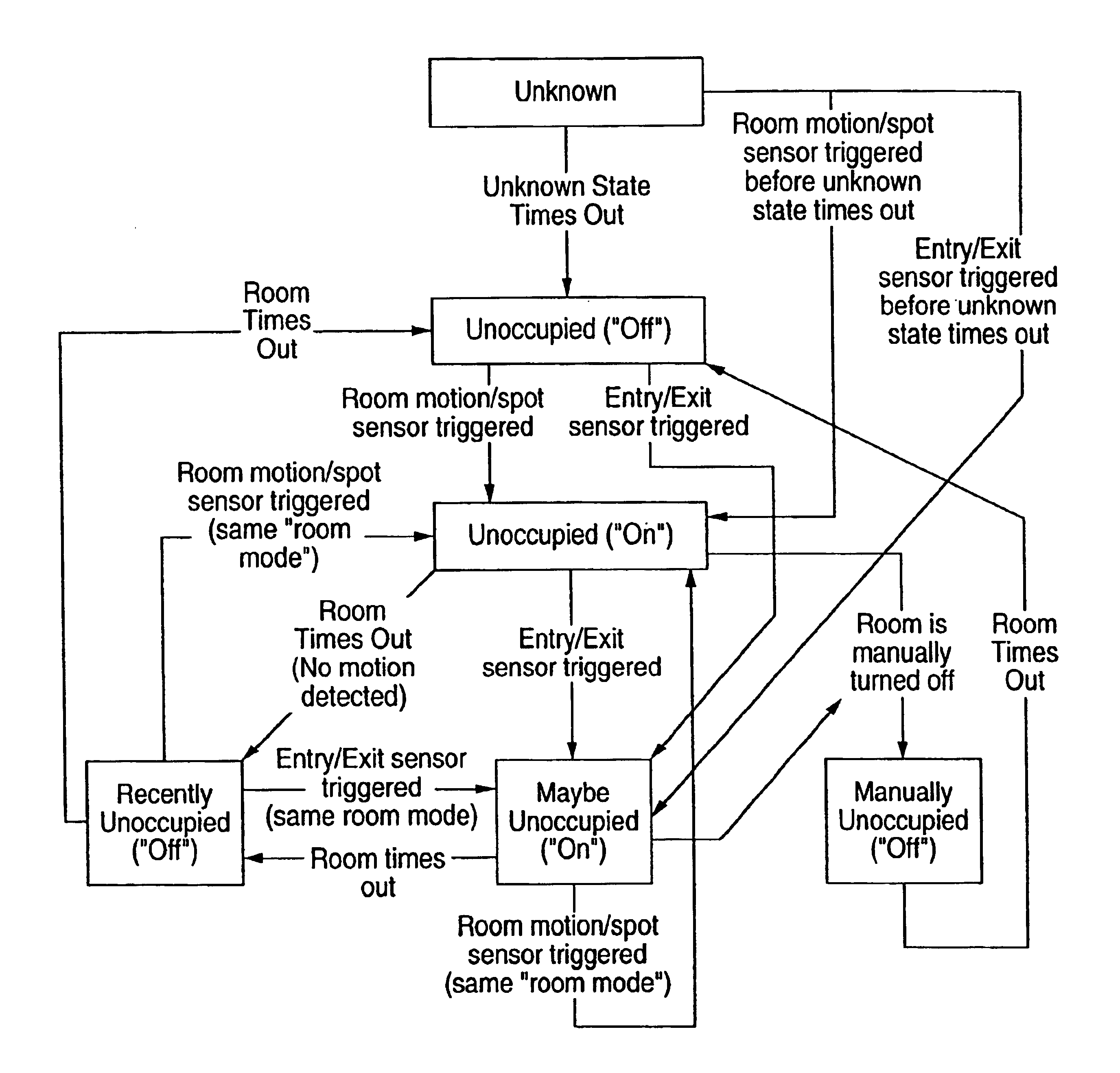
So, for example, the ability for different rooms to have different states and modes simultaneously for varying how devices are controlled when sensors are triggered, or the ability to easily change the operating characteristics of controlled devices, are not found in existing systems because it is so difficult to program such complicated features.
However, for more complicated devices such as
HVAC, whole house audio, surveillance cameras, etc., the
knowledge level required to interface to the hardware exceeds the ability for many home owners.
One characteristic common with most home
automation systems is that when things don't work well, they typically don't work at all.
If the power fails (for longer than a UPS can
handle), or the controlling computer freezes or breaks down, or the
software program has a bug, then it is difficult or impossible to control the controlled devices.
If that module breaks, or the computer that runs the LiteTouch program stops running, or there is a bug in the software, then there is no switch that can turn on these lights.
What is worse is that keypads and remote controller modules replace the standard room light switches, so new users or visitors to a home that are not familiar with the
home automation system will be unable to intuitively perform such basic functions as turning on a light.
Existing solutions further lack a good Internet interface.
Because each house has a customized program running it, it is difficult to provide a
generic interface that provides much value, nor is it easy to teach each home owner or installer how to write web-enabled programs.
Existing home
automation solutions also cannot be massively deployed or supported.
While individual products such as X.10 light switches have broad
market acceptance, the house-specific program and lack of
plug and play software make it impossible to massively deploy any of today's solutions.
Similarly, it is impossible to develop a leverageable support model for today's custom solutions.

