Internal combustion engine, control apparatus for internal combustion engine, and control method for internal combustion engine

a control apparatus and internal combustion engine technology, applied in electrical control, exhaust gas control, speed sensing governors, etc., can solve the problems of increasing the load on the engine, the exhaust gas control catalyst does not fully perform the function, and the load of electric power generation performed by an alternator increases, so as to prevent a reduction in the engine speed

Inactive Publication Date: 2005-07-05
TOYOTA JIDOSHA KK
View PDF6 Cites 21 Cited by
  • Summary
  • Abstract
  • Description
  • Claims
  • Application Information

AI Technical Summary

Benefits of technology

[0027]According to the control method for an internal combustion engine for a vehicle, when the internal combustion engine performs the operation of supplying secondary air, air is delivered into the combustion chamber such that the intake air amount is increased by the increase correction amount. The increase correction amount i

Problems solved by technology

Therefore, when the engine is cold, for example when the engine is started, the exhaust gas control catalyst does not fully perform the function.
Therefore, load for electric power generation performed by an alternator increases, and a load on the engine increases.
When the engine speed thus decreases, idling stability deteriorates during idling imm

Method used


Image

  • Internal combustion engine, control apparatus for internal combustion engine, and control method for internal combustion engine
  • Internal combustion engine, control apparatus for internal combustion engine, and control method for internal combustion engine
  • Internal combustion engine, control apparatus for internal combustion engine, and control method for internal combustion engine

Examples


first embodiment

[First Embodiment]

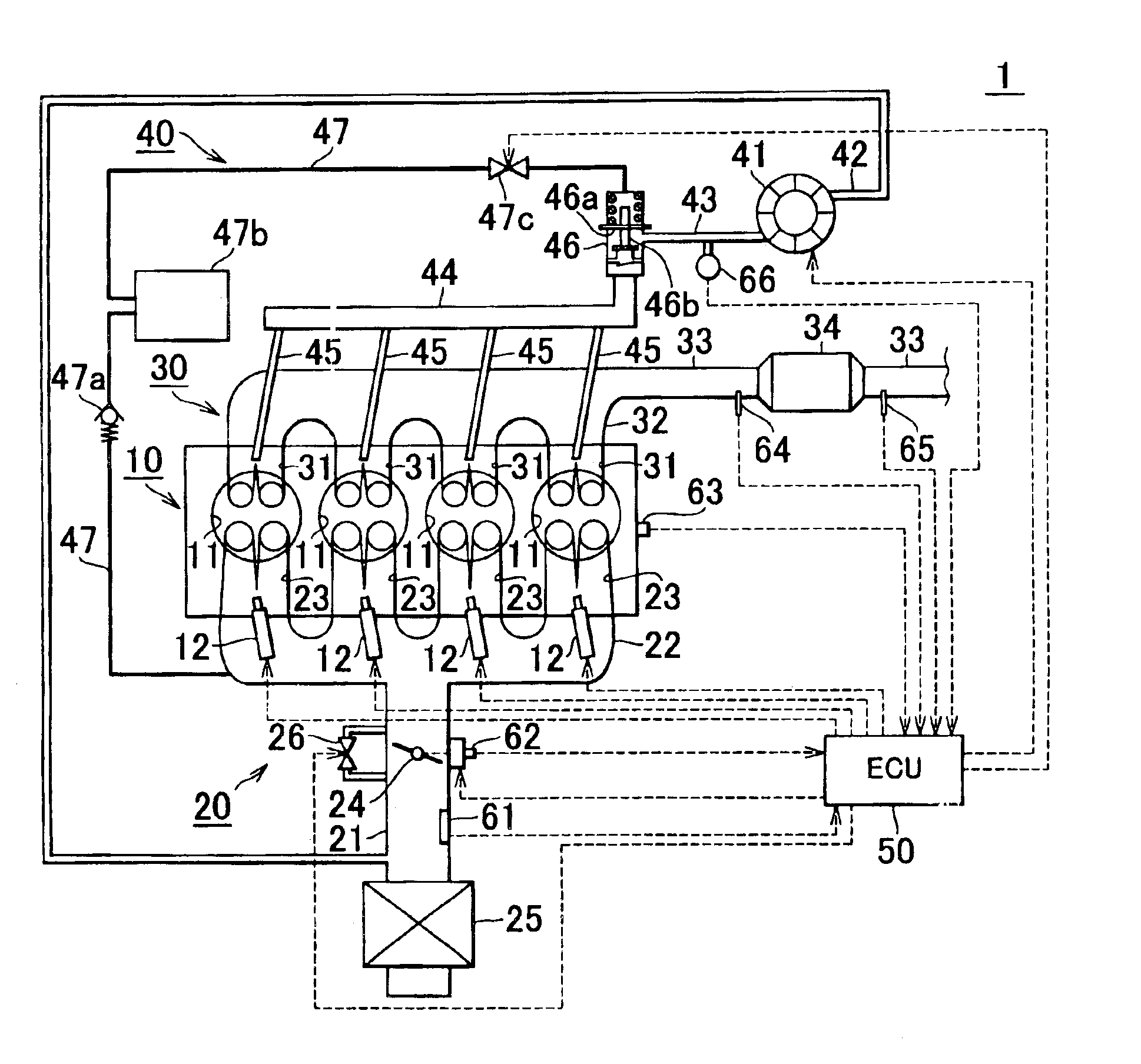
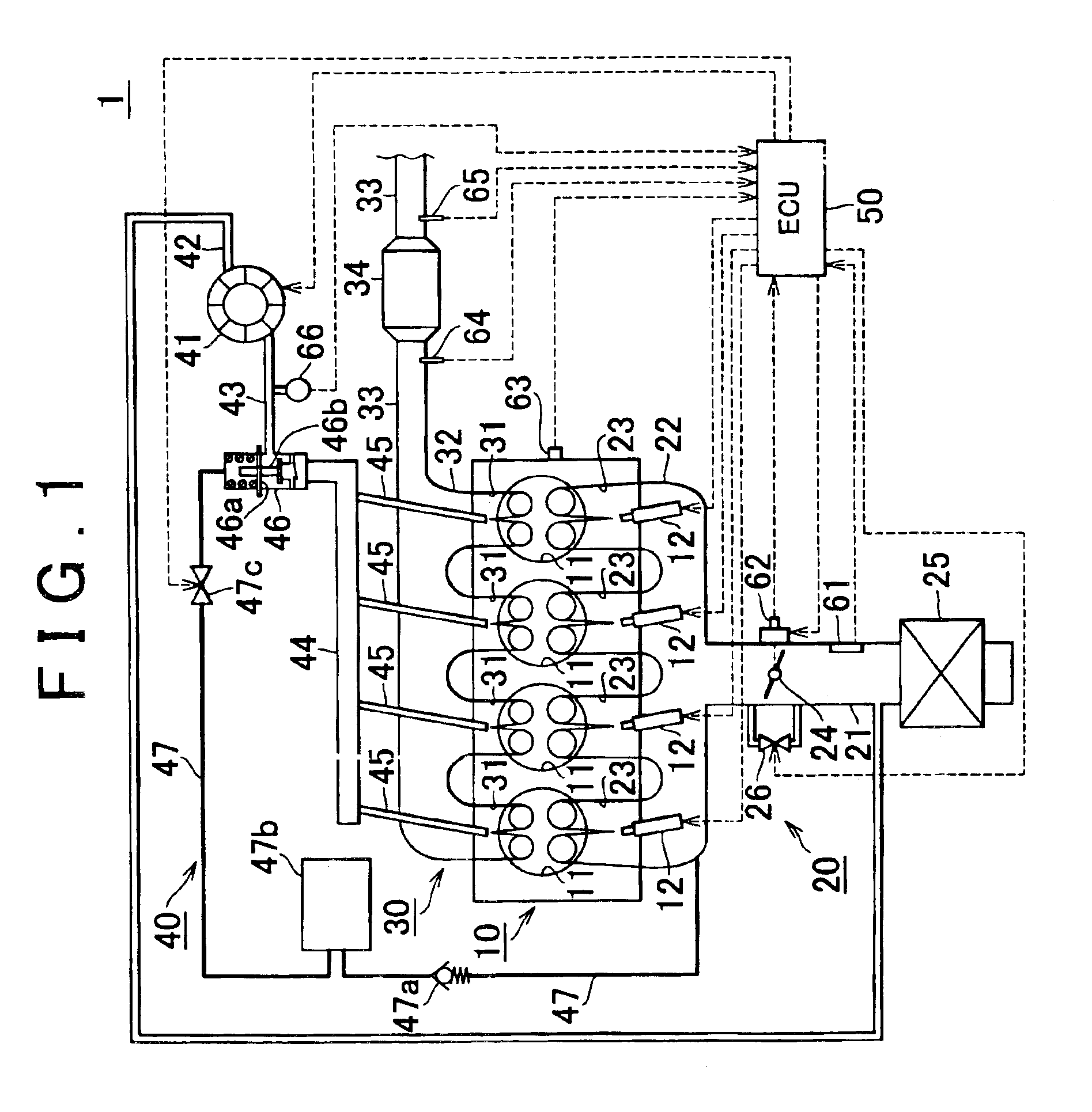
[0035]An internal combustion engine, a control apparatus for an internal combustion engine, and a control method for an internal combustion engine according to a first embodiment will be described with reference to FIG. 1 to FIG. 4. In the embodiment, a configuration will be described in which idle speed control (ISC) is employed as an adjusting device which adjusts an intake air amount delivered to a combustion chamber from an intake pipe.

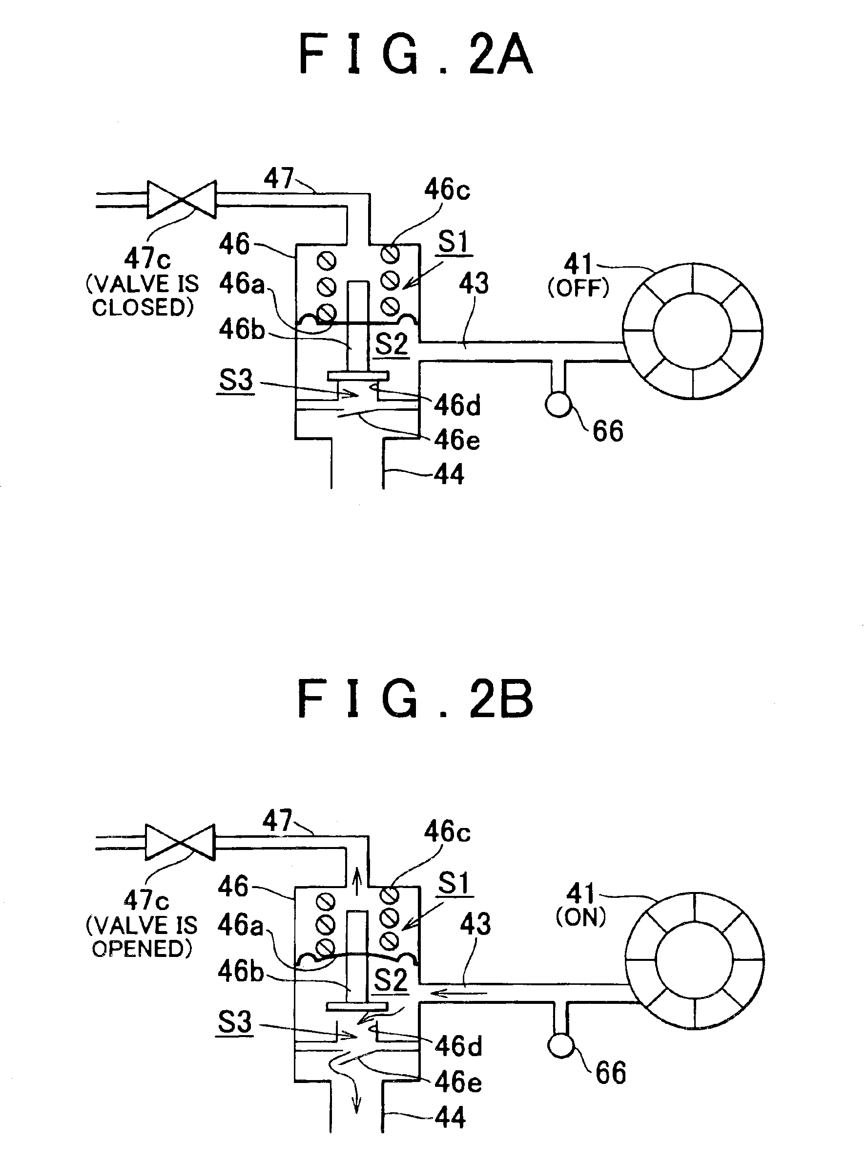
[0036]FIG. 1 is a block diagram showing a basic configuration of an internal combustion engine according to a first embodiment of the invention. FIG. 2 is a diagram describing an operation of a secondary air supply control valve. FIG. 3 is a flowchart of a control process for the internal combustion engine according to the embodiment of the invention. FIG. 4 is a timing chart showing a time-dependent variation in a state change amount or the like at each of portions concerning the internal combustion engine according to the embod...

second embodiment

[Second Embodiment]

[0121]FIG. 5 shows a basic configuration of an internal combustion engine according to a second embodiment of the invention. In the first embodiment, the idle speed control (ISC) is employed as the adjusting device which adjusts the intake air amount delivered into the combustion chambers from the intake pipe. In the second embodiment, the electronic control throttle system is employed as the adjusting device.

[0122]Since the other configurations and effects are the same as in the first embodiment, the same components are denoted by the same reference numerals, and the description thereof will be omitted.

[0123]In the second embodiment, a throttle valve 27 provided in the intake pipe 21 is an electronic controlled butterfly valve whose opening is changed according to a command signal from the ECU 50 and which adjusts the area of the flow passage for the intake air (i.e., adjusts the flow amount).

[0124]The opening of the throttle valve 27 is decided based on the depr...


PUM


Abstract

An internal combustion engine includes an air pump that supplies secondary air to an upstream side of an exhaust gas control catalyst in an exhaust pipe via a secondary air supply passage; an adjusting device that adjusts an intake air amount delivered into a combustion chamber from an intake pipe; and a controller that performs control for increase correction of the intake air amount adjusted by the adjusting device when the air pump performs an operation of supplying the secondary air. Thus, it is possible to prevent a problem caused by a reduction in an engine speed due to the secondary air supply.

Description

INCORPORATION BY REFERENCE[0001]The disclosure of Japanese Patent Application No. 2002-261082 filed on Sep. 6, 2002, including the specification, drawings and abstract is incorporated herein by reference in its entirety.BACKGROUND OF THE INVENTION[0002]1. Field of the Invention[0003]The invention relates to an internal combustion engine including a secondary air supply mechanism, a control apparatus for the internal combustion engine, and a control method for the internal combustion engine.[0004]2. Description of the Related Art[0005]A conventional exhaust gas control structure is known, in which an exhaust gas control catalyst is provided in an exhaust pipe of an internal combustion engine. The exhaust gas control catalyst has a function of transforming air pollutants such as HC, CO, NOx, and the like that are contained in exhaust gas into harmless H2O, CO2, N2, and the like.[0006]However, the exhaust gas control catalyst needs to be placed in an environment at a given activation t...

Claims


Application Information

Patent Timeline
IPC IPC(8): F01N3/30F02D41/14F01N3/32F02D41/02F02D31/00F01N11/00F02D41/06F01N3/22F02D41/08
CPCF01N3/32F01N11/007F02D31/002F02D31/003F02D41/024F02D41/1441F01N2430/06F01N2570/10F01N2570/12F01N2570/14F02D41/06F02D41/1454Y02T10/26Y02T10/47Y02A50/20Y02T10/12Y02T10/40
Inventor HIROOKA, SHIGEMASA
Owner TOYOTA JIDOSHA KK
Why Eureka
Try Eureka