Torch igniter

a technology of torch igniter and torch, which is applied in the direction of engine starter, ignition of turbine/propulsion engine, lighting and heating apparatus, etc., can solve the problems of not being able to place the igniter relative, favorable aerodynamic conditions, and the light of the combustion engine o

Inactive Publication Date: 2005-07-05
THE BOEING CO
View PDF13 Cites 30 Cited by
  • Summary
  • Abstract
  • Description
  • Claims
  • Application Information

AI Technical Summary

Problems solved by technology

If the rate of heat loss from the kernel is less than the rate of heat production in the kernel, the ignition front advances leading to combustor light-off.
Some combustors, however, are engineered to operate with inlet conditions (e.g., during supersonic pre-ignition flow) and / or fuel conditions (e.g., fuel type, fuel droplet size, the extent to which the fuel and air have mixed) that do not present the favorable aerodynamic conditions that are necessary for reliable ignition and flame propagation with conventional igniters.
Further aggravating this situation, it may not be practical to place the igniter relative to the combustor in the position where it would be most effective as when, for example, the placement of the igniter is dictated by concerns for serviceability or the packaging of the combustor into an application.

Method used


Image

  • Torch igniter
  • Torch igniter
  • Torch igniter

Examples


Embodiment Construction

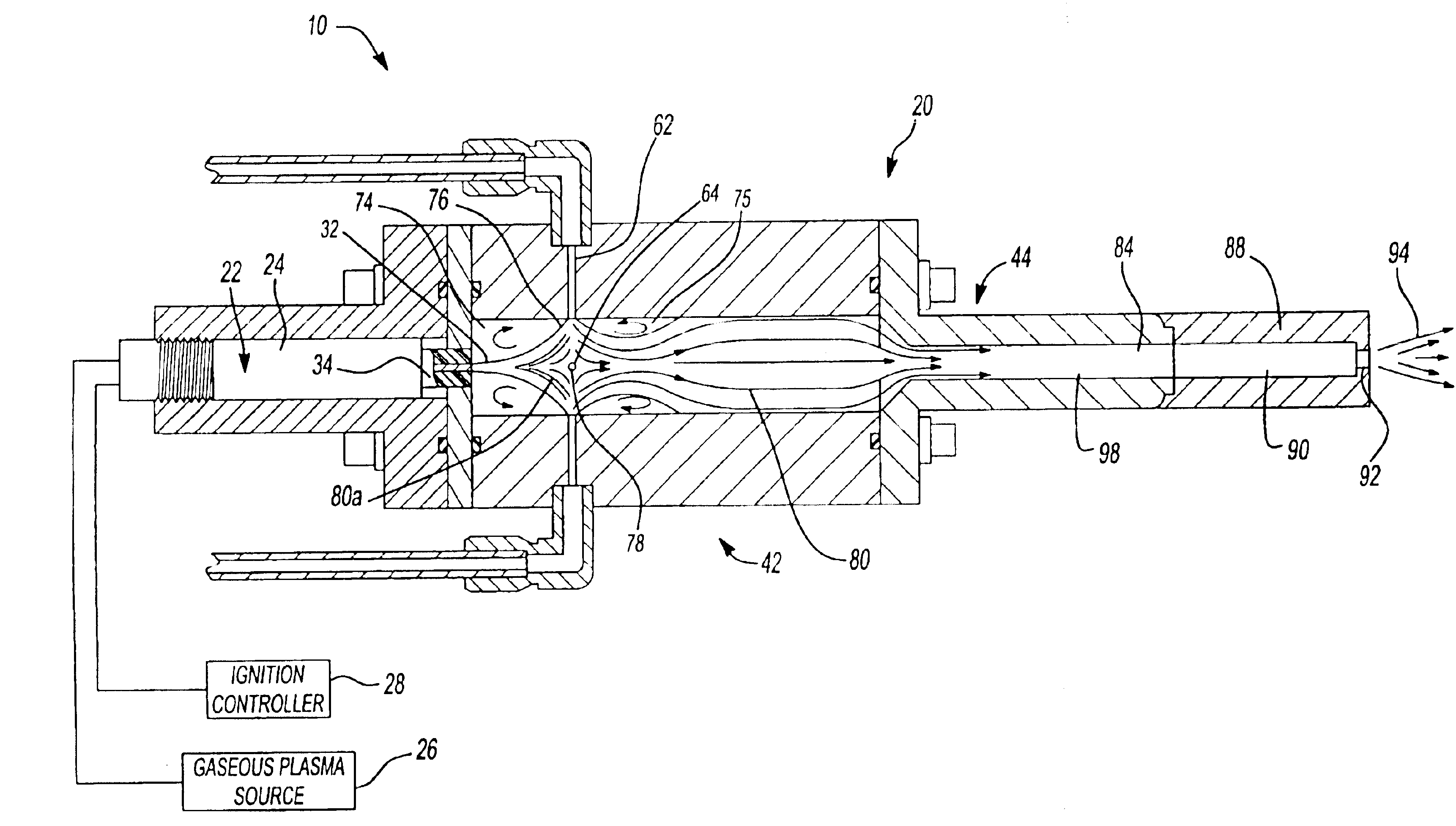
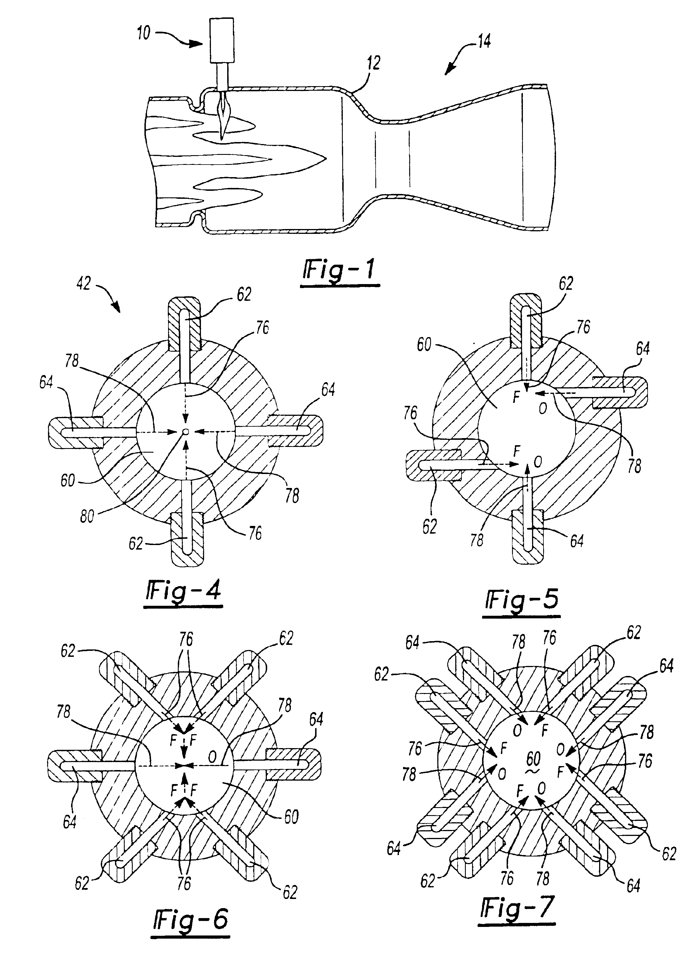
[0017]With reference to FIG. 1 of the drawings, a torch igniter constructed in accordance with the teachings of the present invention is generally indicated by reference numeral 10. The torch igniter 10 is especially suited to produce a high concentration of free radicals at a high temperature and appropriate mass flux that is required for generating a robust ignition event in the combustor 12 of a device such as a thrust augmenter 14, a turbojet engine, a ramjet engine, a combined-cycle engine or an industrial burner. In the particular embodiment provided, the torch igniter 10 utilizes an ethylene fuel and an air or oxygen oxidizer so as to produce free radicals such as OH, H and O and a robust output torch jet or kernel.

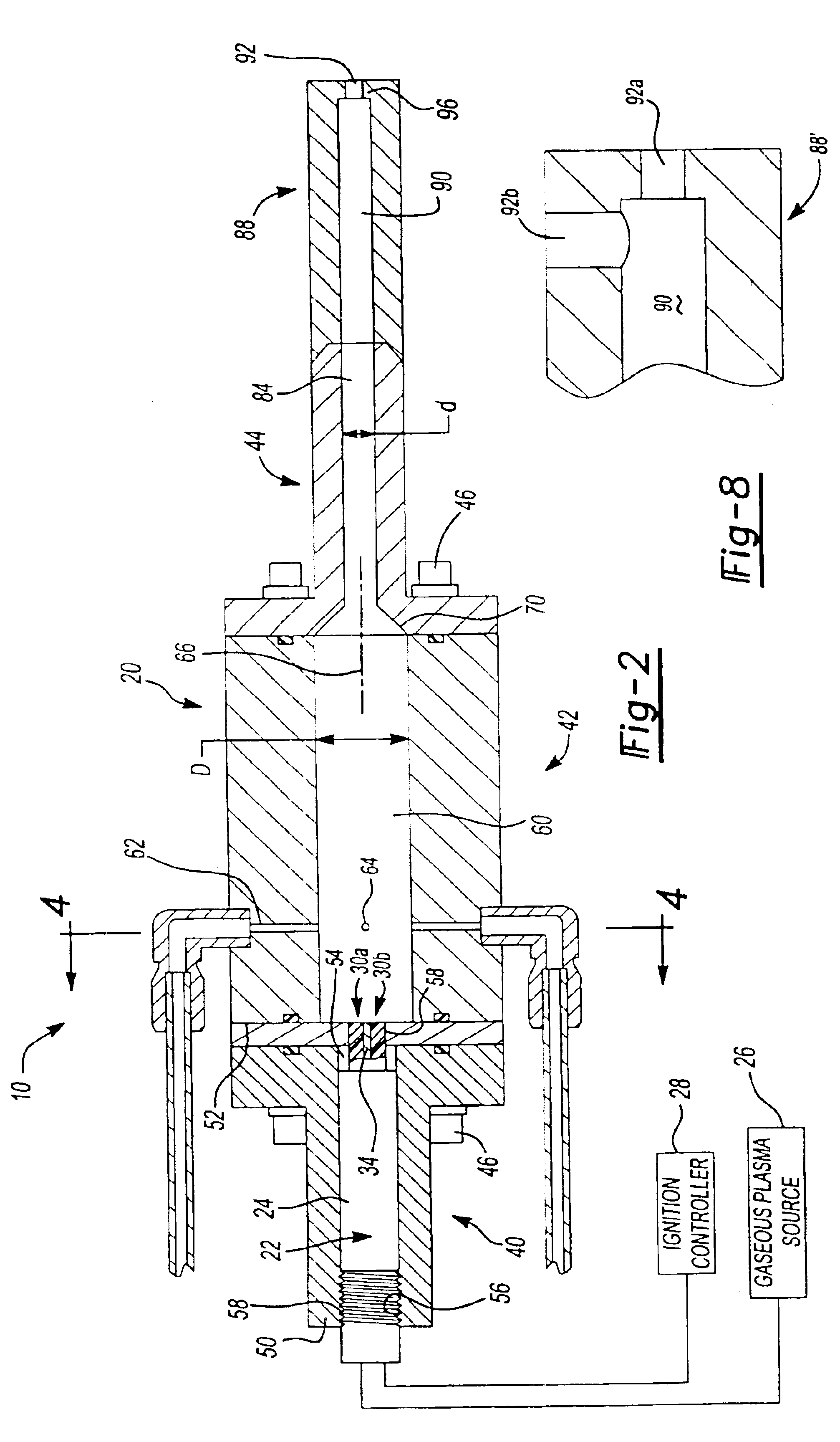
[0018]With additional reference to FIGS. 2 and 3, the torch igniter 10 is illustrated to include a housing 20 and an electronic ignition source 22, which is illustrated to be a conventional and commercially available plasma jet igniter 24, such as a plasma jet igni...


PUM


Abstract

An improved torch igniter for use in devices such as thrust augmenters, gas turbine engines, ramjets, combined-cycle engines and industrial burners. The torch igniter includes a housing with a combustion chamber. Fuel and oxidizer are delivered into the combustion chamber and ignited by an electronic ignition source, such as a plasma jet igniter or a spark igniter, so that an upstream recirculation zone and a downstream recirculation zone are created. The upstream recirculation zone stabilizes and pilots combustion within the combustion chamber, while the downstream recirculation zone augments the combustion event. Byproducts of the combustion event within the torch igniter provide a high mass flux with high thermal energy and strong ignition source radicals that are discharged through a neck portion of the housing and are thereafter employed to initiate a primary combustion event in a primary combustor.

Description

CROSS REFERENCE TO RELATED APPLICATIONS[0001]This application is a divisional Ser. No. 10 / 217,972 filed on Aug. 13, 2002, of U.S. Pat. No. 6,748,735 issued on Jun. 15, 2004. The disclosure of the above application is incorporated herein by reference in its entirety into the present application.FIELD OF THE INVENTION[0002]The present invention generally relates torch igniters for initiating a combustion event in devices such as industrial burners or combustors for gas turbine engines, ramjets or combined-cycle engines, and more particularly to a torch igniter having increased mass flux and energy.BACKGROUND OF THE INVENTION[0003]Conventional aircraft engines, ramjets, combined-cycle engines and industrial burners typically include an electronically actuated ignition source for initiating a combustion event in a combustion chamber. Such electronically actuated ignition sources are usually of the spark igniter type or the plasma jet type.[0004]Spark igniters typically utilize a spark p...

Claims


Application Information

Patent Timeline
Patent Type & Authority Patents(United States)
IPC IPC(8): F23Q13/00
CPCF23Q13/00
Inventor SCHMOTOLOCHA, STEPHEN N.MORRIS, DONALD H.MORRISON, JR., CALVIN Q.PEDERSON, ROBERT J.
Owner THE BOEING CO
Why Eureka
Try Eureka