Closed kneader

a closed kneading and kneading technology, which is applied in the direction of clay mixing apparatus, mixing/kneading with horizontally mounted tools, transportation and packaging, etc., can solve the problems of high temperature of kneaded material at the end of primary kneading, and constituted a productivity obstruction factor, so as to reduce the thickness of kneaded material and achieve sufficient cooling

Inactive Publication Date: 2005-07-05
MORIYAMA +1
View PDF12 Cites 12 Cited by
  • Summary
  • Abstract
  • Description
  • Claims
  • Application Information

AI Technical Summary

Benefits of technology

[0015]The third invention constructed as above can reduce the thickness of the kneaded material as much as possible by keeping the clearance between the outer circumferential face of t...

Problems solved by technology

However, with a conventional closed kneader, the temperature of the kneaded material remains high at the end of the primary kneading because ...

Method used


Image

  • Closed kneader
  • Closed kneader
  • Closed kneader

Examples


Embodiment Construction

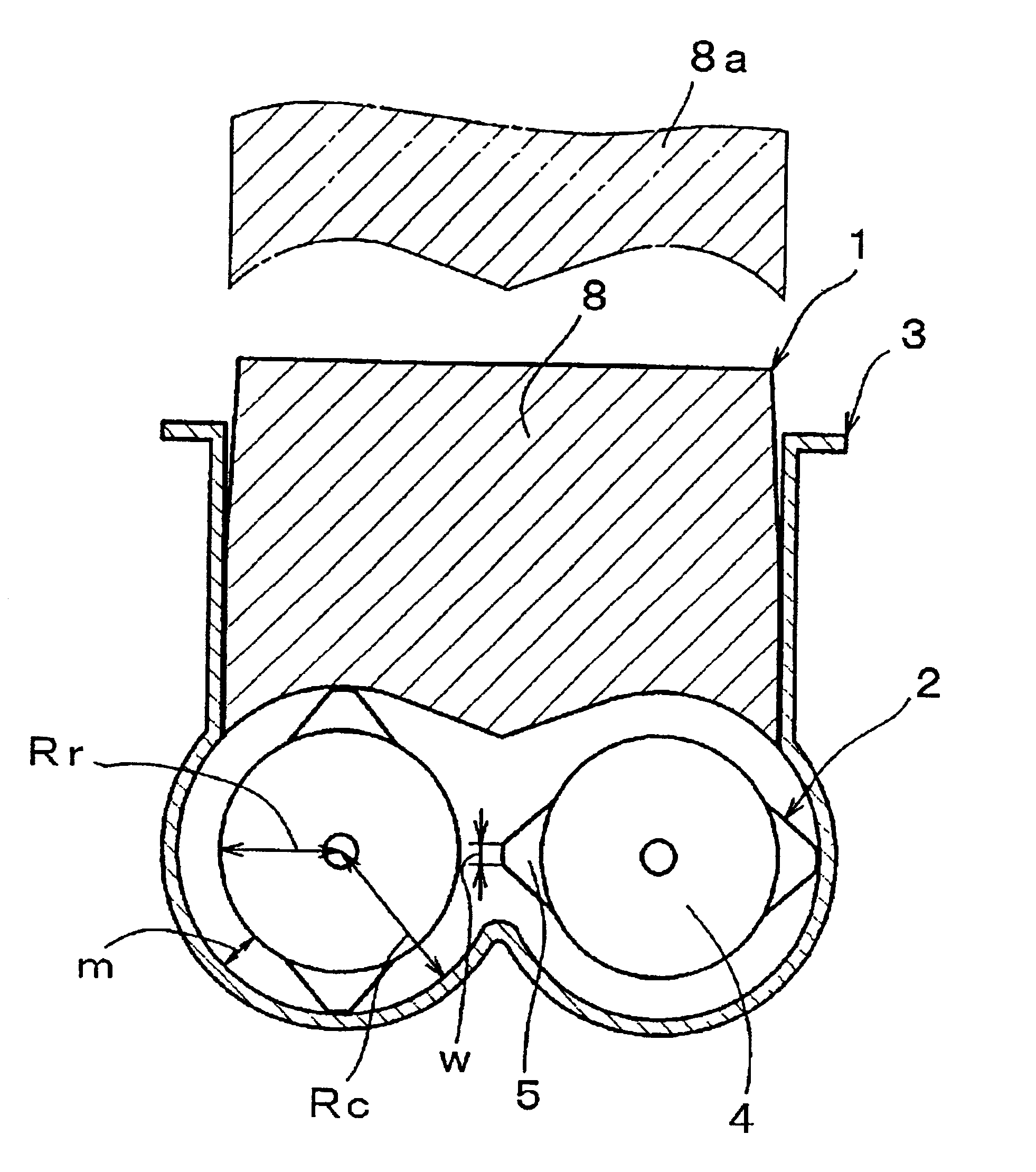
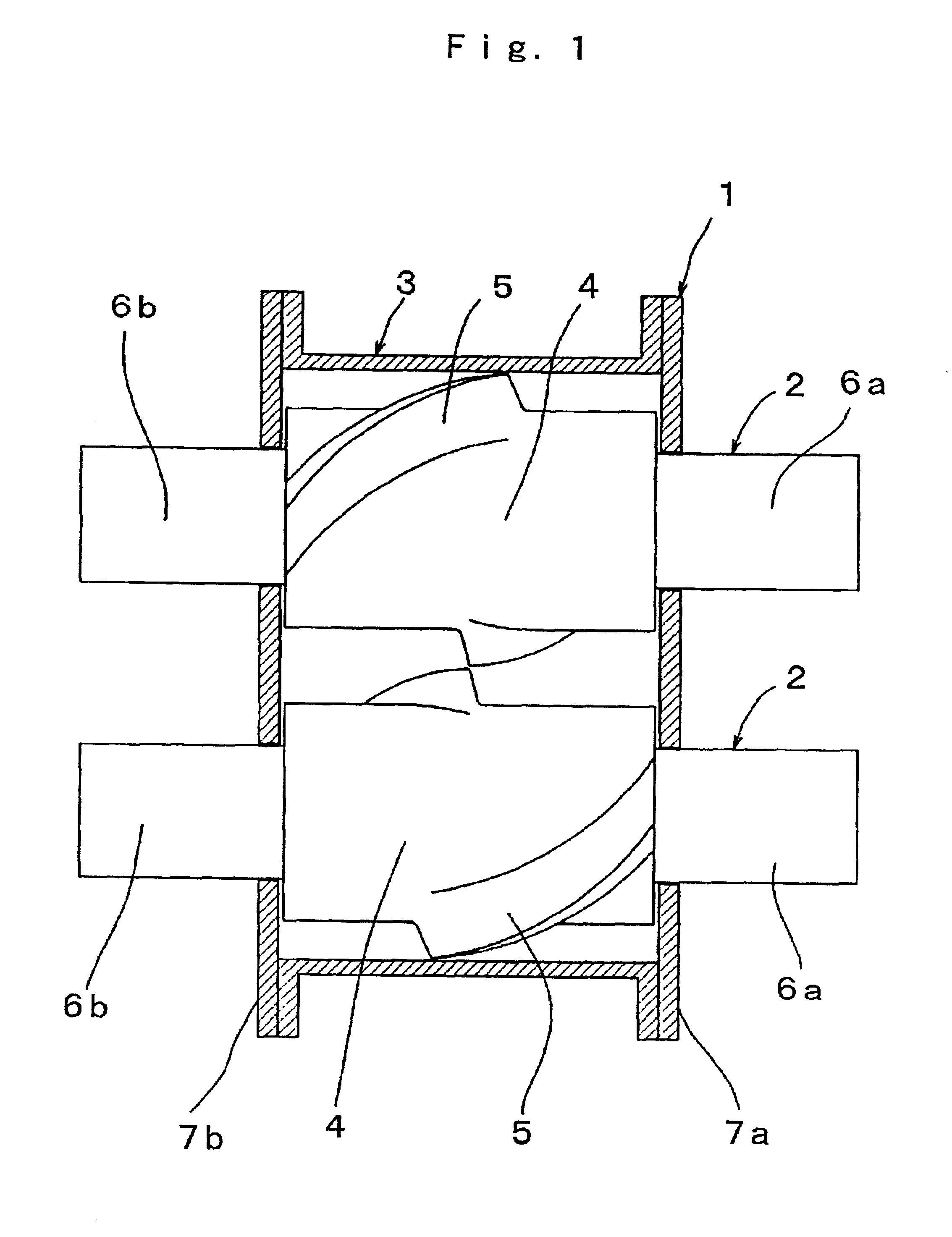
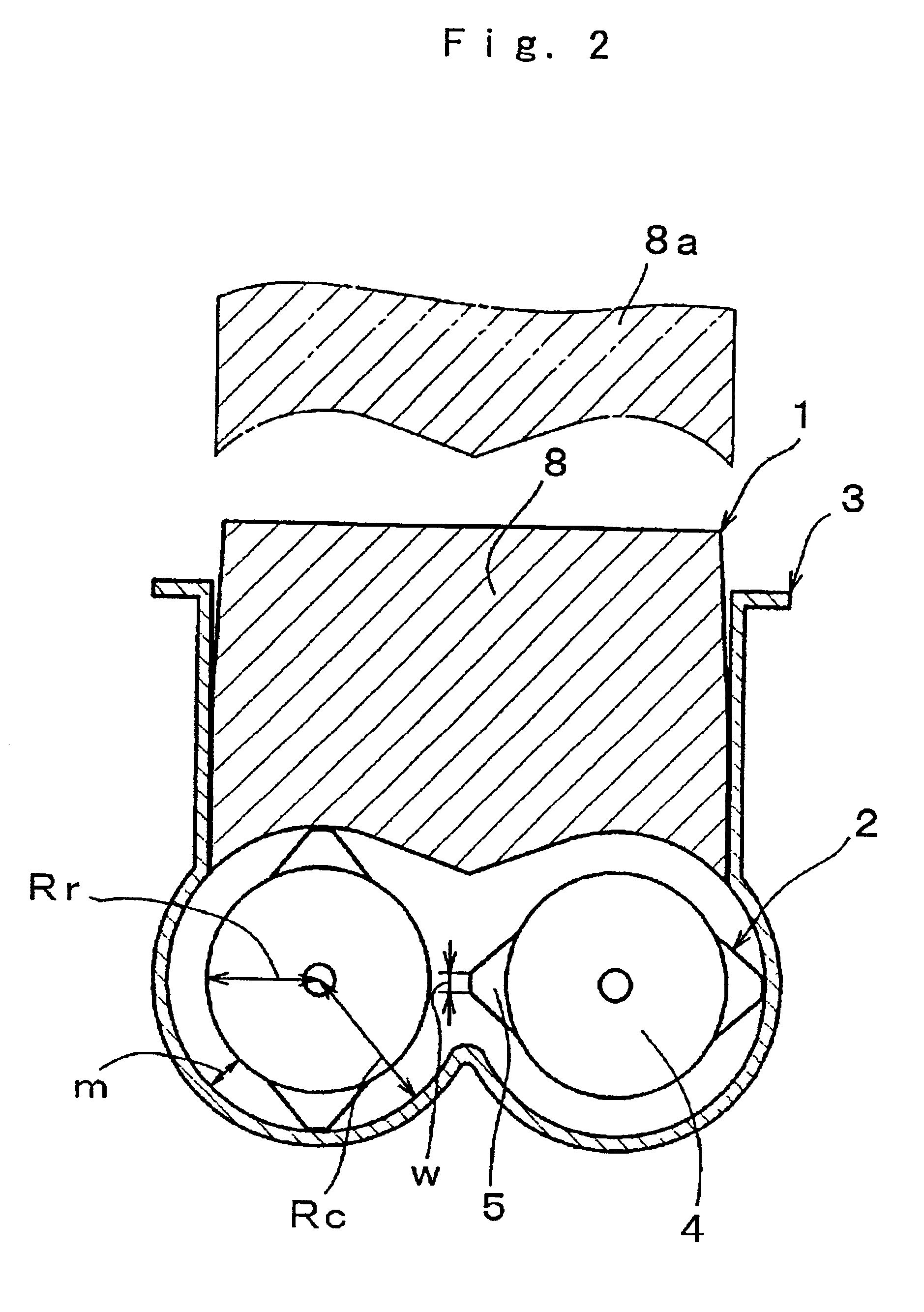
[0024]The present invention will be explained hereafter based on the embodiment indicated in FIG. 1 to FIG. 3. In the drawings, a closed kneader 1 is an example of a pressure kneader, the rotor of which is mounted tangentially. In the same way as the known mechanism (the same symbol will be used for the same structure and repeated explanation will be omitted), the present invention is comprised of a chamber 3 for storing kneaded material, a pair of rotors 2, 2, which are provided at both ends with rotor drive shafts 6a, 6b passing through side walls 7a, 7b of the chamber 3 and which consist of a rotor shaft 4 forming a rotor blade 5 for kneading the kneaded material in the chamber 3 and a pressure cover 8.

[0025]The rotor blades 5, 5 on the pair of rotors 2, 2 are preferably disposed tangentially in a way so as not to overlap with each other, as shown in FIG. 1.

[0026]However, the closed kneader 1 according to the present invention is realized by keeping the proportion of the radius o...


PUM

PropertyMeasurementUnit
Fractionaaaaaaaaaa
Temperatureaaaaaaaaaa
Radiusaaaaaaaaaa

Abstract

With conventional closed kneaders, the temperature of the kneaded material remains high at the end of primary kneading because insufficient cooling is made in the interior part of the kneaded material, making it necessary to either provide cooling time between the primary and secondary kneading or to transfer materials to another kneader after the end of primary kneading for the secondary kneading. This has constituted an obstruction to productivity. In view of such problems, a closed kneader is capable of controlling the kneaded material temperature at the end of primary kneading at a level no higher than the temperature that allows addition of a vulcanizing agent line, and can perform secondary kneading immediately after the end of primary kneading. In a closed kneader provided with a chamber for storing kneaded material and a pair of rotors installed in the chamber, the proportion of the radius of the rotor shaft to the radius on the inner face of the chamber is kept at no less than 0.65.

Description

BACKGROUND OF THE INVENTION[0001]The present invention concerns a closed kneader for kneading viscous materials such as plastic, rubber, etc., and more specifically the shape of the rotor shaft thereof.[0002]An example of a conventional closed kneader is indicated in FIG. 4 and FIG. 5. In the drawings, a closed kneader 50 is composed of a kneading tank (hereinafter referred to as “chamber 3”) for holding kneaded material, a pair of rotors 51, 51, which are provided at both ends with rotor drive shafts 54a, 54b (hereinafter simply referred to as 54 when generically mentioned) passing through side walls 7a, 7b of the chamber 3, and which consist of a rotor shaft 52 forming a rotor blade 53 for kneading the material kneaded in the chamber 3, and a pressure cover 8. When kneading material, the kneaded material is poured into the chamber 3 by a proper means in a state where the pressure cover 8 is opened upward (see the position of 8a in FIG. 4), the pressure cover 8 is let down (see the...

Claims


Application Information

Patent Timeline
IPC IPC(8): B01F7/02B01F7/08B29B7/28B29B7/02B29B7/18B01F7/00
CPCB01F7/082B29B7/183B29B7/186B29B7/28B01F7/00425B01F2215/0431B01F2215/0472B29B7/7495B29B7/82B01F27/1144B01F27/722
Inventor OTSUKA, TOSHIYUKIIRIE, MAKOTO
Owner MORIYAMA
Why Eureka
Try Eureka