Air purifier

Inactive Publication Date: 2005-07-05
SAMSUNG ELECTRONICS CO LTD
View PDF22 Cites 34 Cited by
  • Summary
  • Abstract
  • Description
  • Claims
  • Application Information

AI Technical Summary

Benefits of technology

[0008]Accordingly, it is an aspect of the present invention to provide an air purifier which is designed to discharge air directly to a room without forcing the air to pass through a HEPA filter when the level of cont

Problems solved by technology

However, in the conventional air purifier, the HEPA filter functioning to filter microparticles, such as fine dust, bacteria or fungi, must have a microstructure necessary for filtering the microparticles, so the HEPA filter generates high resistance against air currents circulated through the air purifier, and thus causes a high degree of air pressure loss, even though the HEPA filter has high air-purifying efficiency.
Due to the high degree of air pressure loss caused by the HEPA filter, purified air cannot be distributed to areas distant from the air purifier.
In

Method used


Image

  • Air purifier
  • Air purifier
  • Air purifier

Examples


first embodiment

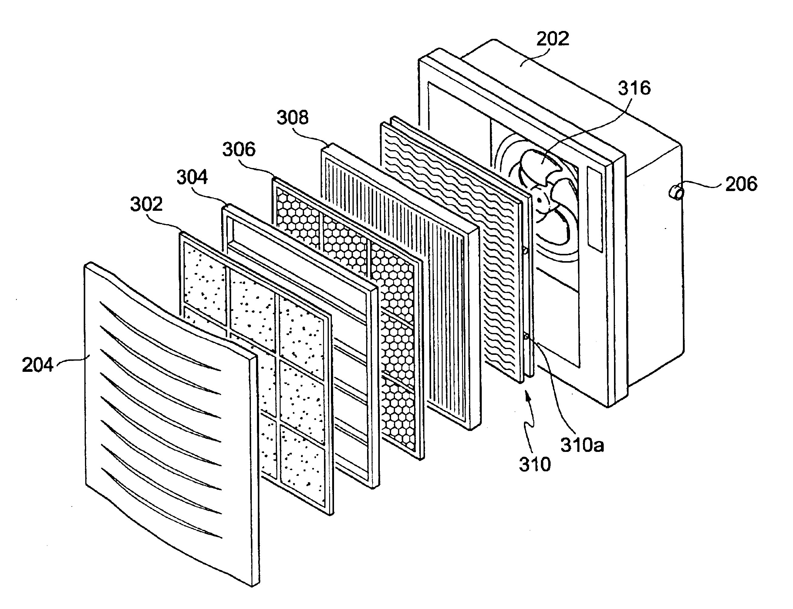
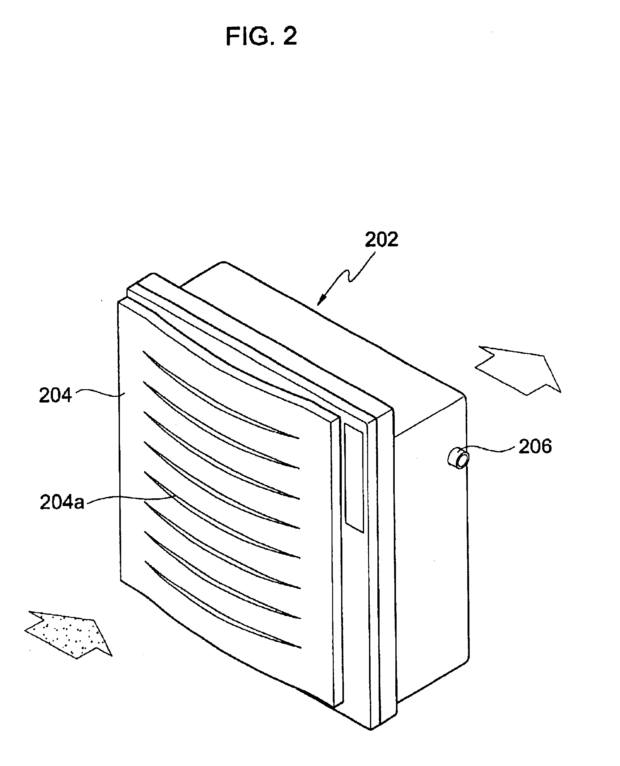
[0023]Embodiments of an air purifier according to the present invention are described in detail with reference to FIGS. 2 to 9. FIG. 2 is a perspective view of an air purifier, according to the present invention. As shown in FIG. 2, a main body 202 of the air purifier is equipped with a cover 204 at a front surface thereof, in which the cover 204 is formed with a plurality of air suction slits 204a so that external air is sucked into the main body 202. That is, through the air suction slits 204a, contaminated air is sucked into the main body 202 which functions to remove contaminants, such as dust particles, hazardous components and offensive odors, thus purifying the contaminated air. The purified air is discharged through an air exhaust port (not shown) positioned at a back surface of the main body 202 to the outside of the air purifier. At a side surface of the main body 202, a contamination level sensor 206 is mounted to determine the contamination level of air inside a room hav...

second embodiment

[0032]FIGS. 7 to 9 are views of an air purifier provided with a bypass passage on a main body thereof, according to the present invention. As shown in FIG. 7, which is a perspective view of the air purifier, the main body 702 of the air purifier is equipped with a cover 704 at a front surface thereof, in which the cover 704 is formed with a plurality of air suction slits 704a so that external air is sucked into the main body 702. That is, through the air suction slits 704a, contaminated air is sucked into the main body 702, which functions to remove contaminants such as dust particles, hazardous components, and offensive odors, thus purifying the contaminated air. The purified air is discharged through an air exhaust port (not shown), positioned at a back surface of the main body 702, to the outside of the air purifier. At a side surface of the main body 702, a contamination level sensor 706 is mounted to determine the contamination level of air inside a room having the air purifier...


PUM

PropertyMeasurementUnit
Efficiencyaaaaaaaaaa

Abstract

An air purifier includes a main body defining an air passage therein to allow sucked air to pass therethrough prior to being discharged, and a first filter installed in the main body to be switched between a closed state and an open state. The first filter removes contaminants from the sucked air in the closed state, and allows the sucked air to pass through the air passage in the open state. The air purifier may include a main body to suck and discharge air, with a bypass passage formed in the main body so that the bypass passage is opened or closed by a door, and a first filter installed in the main body. The sucked air passes through the first filter prior to being discharged when the door is closed, and passes through the bypass passage prior to being discharged when the door is opened.

Description

CROSS-REFERENCE TO RELATED APPLICATION[0001]This application claims the benefit of Korean Application No. 2002-82693, filed Dec. 23, 2002, in the Korean Intellectual Property Office, the disclosure of which is incorporated herein by reference.BACKGROUND OF THE INVENTION[0002]1. Field of the Invention[0003]The present invention relates, in general, to air purifiers and, more particularly, to an air purifier for use in providing dean air by removing dust, bacteria and contaminants from the air.[0004]2. Description of the Related Art[0005]As is well known to those skilled in the art, an air purifier is used to provide purified clean air by removing dust, bacteria and contaminants from the air. The air purifier is provided with a dust collecting, unit to collect dust, and the like. In the dust collecting unit, dust particles electrically charged by corona discharge of an ionizer are collected by electrostatic attraction of a collector having a polarity opposite to a polarity of the char...

Claims


Application Information

Patent Timeline
IPC IPC(8): F24F13/00F24F13/28F24F3/16F24F1/00B01D46/00B01D46/10B01D46/54B03C3/011B03C3/36F24F8/80
CPCB01D46/0023B01D46/10B01D46/54B03C3/011B03C3/36F24F3/16F24F13/28B01D46/0032Y02B30/78B01D2267/40B01D2273/14B01D2273/30F24F2001/0096F24F2003/1682F24F2011/0023F24F2110/64F24F1/0071F24F8/30Y02B30/70B01D46/62F24F8/80B01D46/00
Inventor KIM, JUNG-HO
Owner SAMSUNG ELECTRONICS CO LTD
Why Eureka
Try Eureka