Image display apparatus

An image display device and a technology for image display, which are applied to projection devices, lighting devices, components of lighting devices, etc., can solve problems such as failures and damage to signal processing voltages, so as to suppress failures or damages and avoid long-term reliability. The effect of reducing stability and improving reliability

Inactive Publication Date: 2003-08-27
MATSUSHITA ELECTRIC WORKS LTD +1
View PDF5 Cites 3 Cited by
  • Summary
  • Abstract
  • Description
  • Claims
  • Application Information

AI Technical Summary

Problems solved by technology

[0027] However, the prior art structure presents the technical problem of requiring additional components (noise suppression filter 15, forced air cooling fan 10, etc.) The high-voltage leads are arranged together in a narrow space, thereby malfunctioning, resulting in damage to the signal processing voltage 9

Method used


Image

  • Image display apparatus
  • Image display apparatus
  • Image display apparatus

Examples


no. 1 example

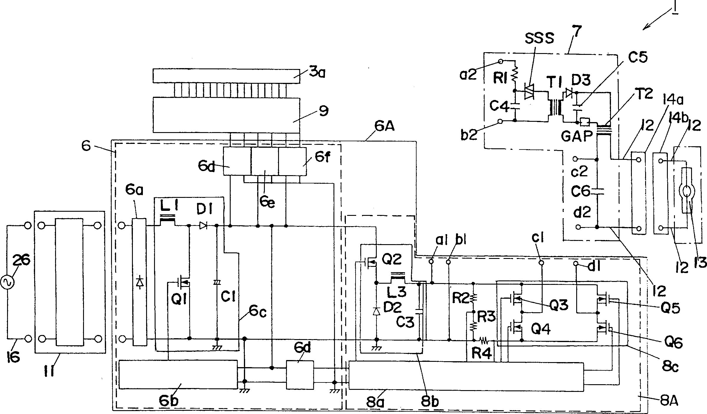
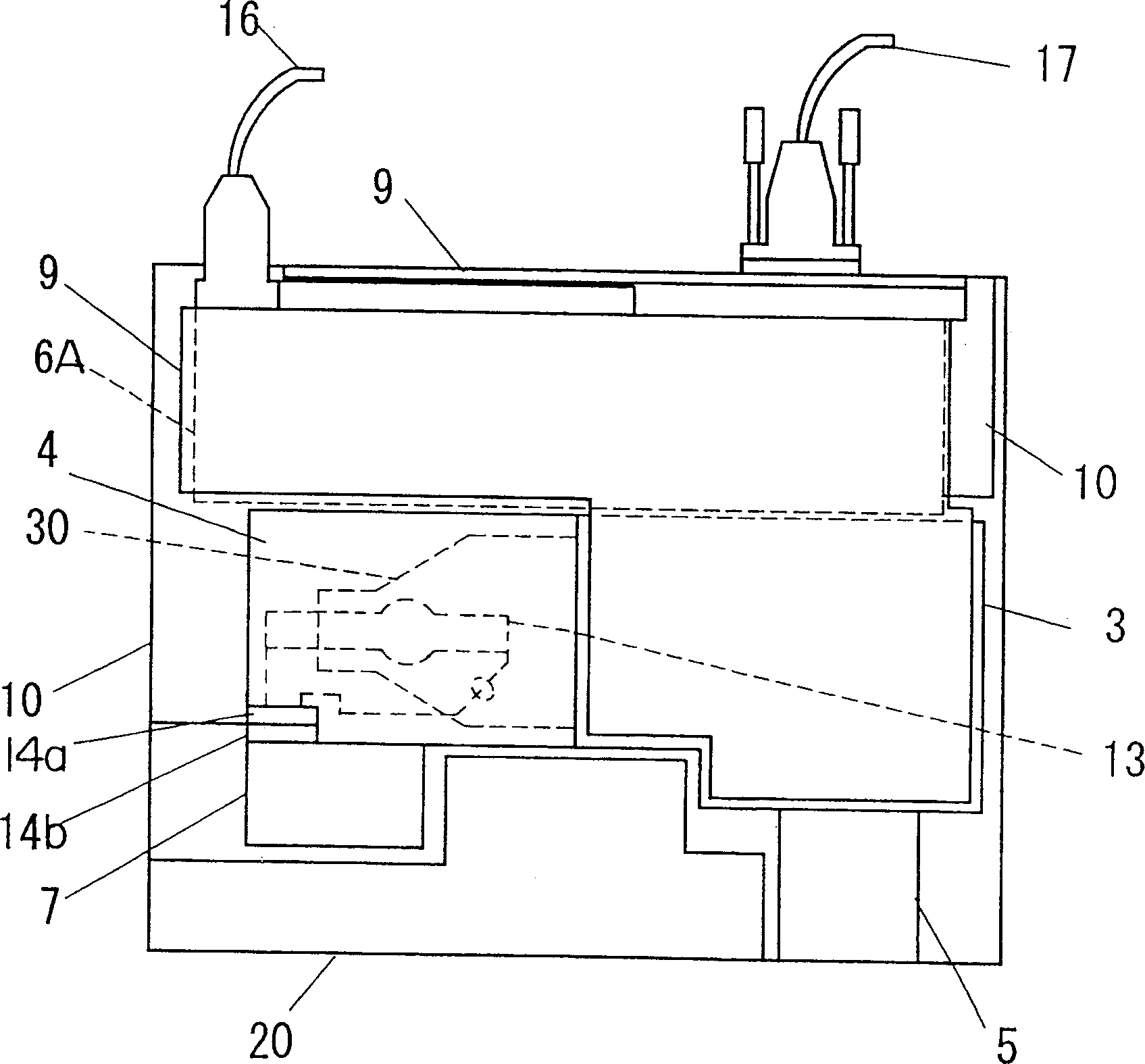
[0066] figure 1 A circuit block diagram showing the image display apparatus according to the first embodiment of the present invention. figure 2 The internal assembly of the above-mentioned image display device is shown.

[0067] The difference between the assembly of the image display device 1 and that of the prior art is that the power supply 6 and the lighting device 8A are mounted on a common circuit board as the combined component 6A, but it does not include the noise filter 15, the capacitor C7 and the trigger The trigger module 7, the lighting device 8A of the combination part 6A is connected to the separate trigger module 7 through the lead bridge between the output terminals (a1-a2) and (b1-b2), and the high voltage lead 12 is made very short. Other assemblies are similar to these explanations, and like numerals are used to designate like parts, and they will not be repeated.

[0068] Since the trigger module 7 is connected to the separately provided lighting devi...

no. 2 example

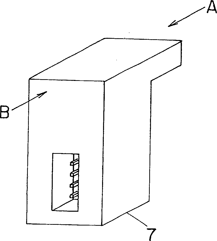
[0074] Figure 3A is a perspective view showing the trigger module, which is shown separated from the assembly part 6A of the image display device according to the second embodiment of the present invention. Figure 3B is a B-directed front view showing the connection terminals (a2, b2, c2, and d2) connected to the assembly part 6A, Figure 3C It is a C-phase front view showing the socket 14 a fixed to the trigger module 7 .

[0075] The difference between the image display device of the second embodiment and the device of the first embodiment is that the trigger module 7 is provided with a lamp socket 14a. Other structures are similar to those of the first embodiment, they are denoted by the same numerals, and their descriptions will not be repeated.

[0076] According to the second embodiment, in which the trigger module 7 includes the lamp socket 14a, it is possible to suppress the high voltage pulse from leaking to other parts through the floating capacitor, thereby supp...

no. 3 example

[0078] The difference between the image display device according to the third embodiment of the present invention and the device of the first embodiment is that the trigger module 7 is connected to the lighting device 8A by wires.

[0079] According to the third embodiment, the trigger module 7 is connected to the lighting device in the combination part 6A by wires, so that a real distance is created between them, thereby obtaining the same effect as in the first embodiment.


PUM


Abstract

A cabinet accommodates therein a discharge lamp 13, an ignitor module 7 applying a high voltage to the discharge lamp 13 for igniting the same, a lighting device 8A which is connected to the ignitor module and applies a discharging voltage to the discharge lamp so as to keep the discharge lamp turned on, a signal processing unit 9 providing an image signal in accordance with an input signal, an image display which, in response to the image signal from the signal processing unit, produces an image to be projected by use of a light of the discharge lamp 13, and a power supply supplying electric power to the above parts. At least a high voltage generating unit of the ignitor module 7 is arranged to be separated from the lighting device 8A and is disposed away from the signal processing unit 9 and close to the discharge lamp 13 for restraining malfunction of the signal processing unit.

Description

technical field [0001] The present invention relates to an image display device for enlarging and projecting images and screens on image display elements such as liquid crystal projectors, DLP projectors, and rear projection TVs. Background technique [0002] refer to Figures 14 to 17 , explaining a projector as an example of an image display device, such as a liquid crystal projector, a DLP projector, which enlarges and projects still images and moving images from a personal computer, video images or TV screens from a video camera or video recorder, and instrument, and a rear projector. [0003] Figure 14 is a perspective view showing the arrangement of components of a conventional projector without a cabinet (indicated by dotted lines instead). Figure 15 Yes Figure 14 Top view of projector internals configuration shown. Fig. 16 shows the structure of the lampshade installed in the projector. Figure 17 is the circuit block diagram of the projector. [0004] Image...

Claims


Application Information

Patent Timeline
Patent Type & Authority Applications(China)
IPC IPC(8): H05B41/04H05B41/288
CPCH05B41/2881Y02B20/204H05B41/042Y02B20/00G03B21/14
Inventor 宫田克生
Owner MATSUSHITA ELECTRIC WORKS LTD
Why Eureka
Try Eureka