Rotating electric machine and method for manufacturing the same

a technology of rotating electric machines and coils, which is applied in the direction of dynamo-electric machines, structural associations, electrical apparatus, etc., can solve the problems of poor material yield, poor material yield, and insufficient contact area in welding, etc., to achieve excellent material yield, excellent bonding with the coil, and the effect of inexpensive rotating electric machines

Inactive Publication Date: 2005-07-05
MITSUBISHI ELECTRIC CORP
View PDF6 Cites 87 Cited by
  • Summary
  • Abstract
  • Description
  • Claims
  • Application Information

AI Technical Summary

Benefits of technology

[0007]This invention is achieved in the light of the above-mentioned problems, and it is an object of the invention to provide a rotating electric machine and a method for manufacturing the rotating electric machine, in which an arm portion integral with a strip conductive portion and extending from a side end portion of the strip conductive portion to be almost parallel in a longitudinal direction is bent in a direction of plate thickness for the strip conductive portion, whereby the yield of material is excellent, the bonding with the coil is excellent, and the rotating electric machine is inexpensive, and is superior in the productivity and performance.

Problems solved by technology

The conventional device constituted in the above manner had a problem that the yield of material was bad formally in any means, even though the materials were appropriately adopted, because the terminal portion juts out from the side end portion of the strip conductor in the direction perpendicular to the longitudinal direction of the strip conductor.
In particular, when the strip conductor is disposed like a concentric circle to allow the terminal portion to jut out beyond other strip conductors on the inner circumferential side and the outer circumferential side, the terminal portion is lengthened, resulting in a problem that the yield of material is worse.
Though the terminal portion has a U-character groove on the side face of the strip conductor, the terminal portion has a contact face with the coil in a plate thickness of the strip conductor, when welded with the coil, resulting in a problem that the large contact area in welding can not be taken for sufficient bonding, and when soldered, a large amount of solder is required, and the heat resistance is lowered to be unsuitable for large current.
Therefore, if the plate thickness of the strip conductor is increased, there is a problem that the strip conductor is increased in size and difficult to work.
Furthermore, the U-character groove had a problem that the coil is difficult to be inserted into the groove.

Method used


Image

  • Rotating electric machine and method for manufacturing the same
  • Rotating electric machine and method for manufacturing the same
  • Rotating electric machine and method for manufacturing the same

Examples


embodiment 1

(Embodiment 1)

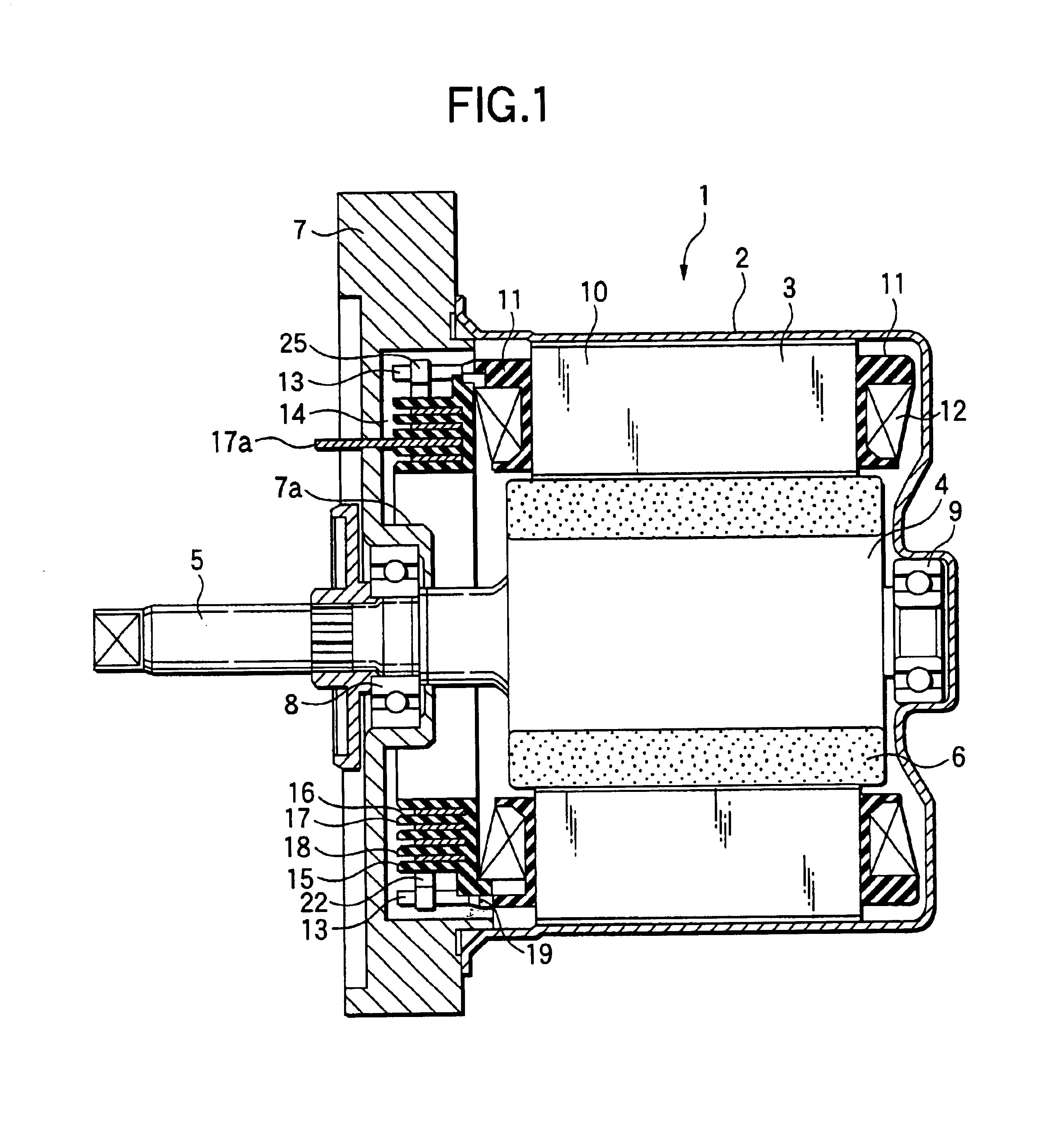
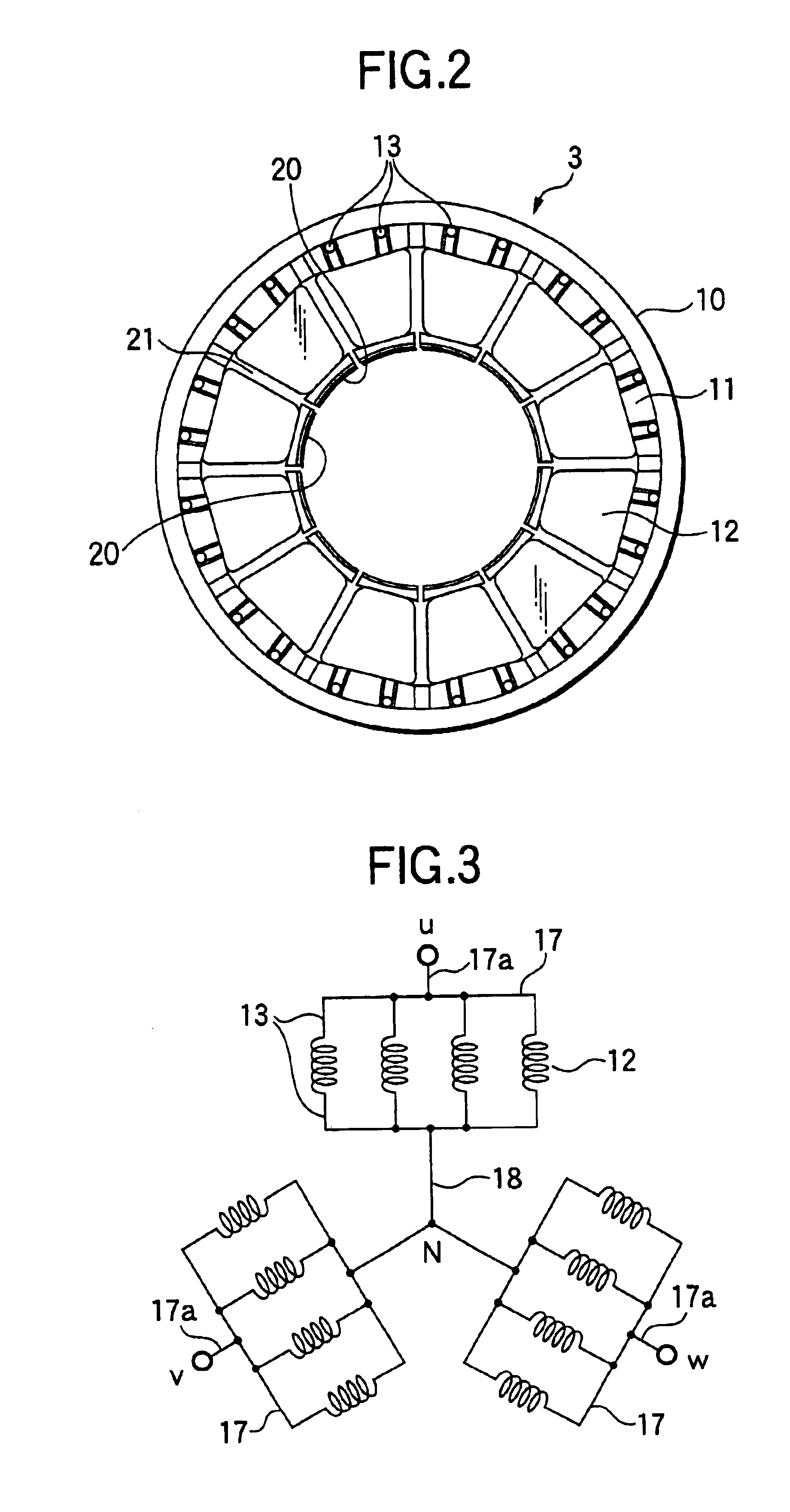
[0061]An embodiment 1 of the present invention will be described with reference to the drawings. FIG. 1 is a cross-sectional view of a brushless motor for electric power steering gear for the vehicle as one example of a rotating electric machine according to the present invention. FIG. 2 is a front view of a stator. FIG. 3 is a connection view of a stator coil.

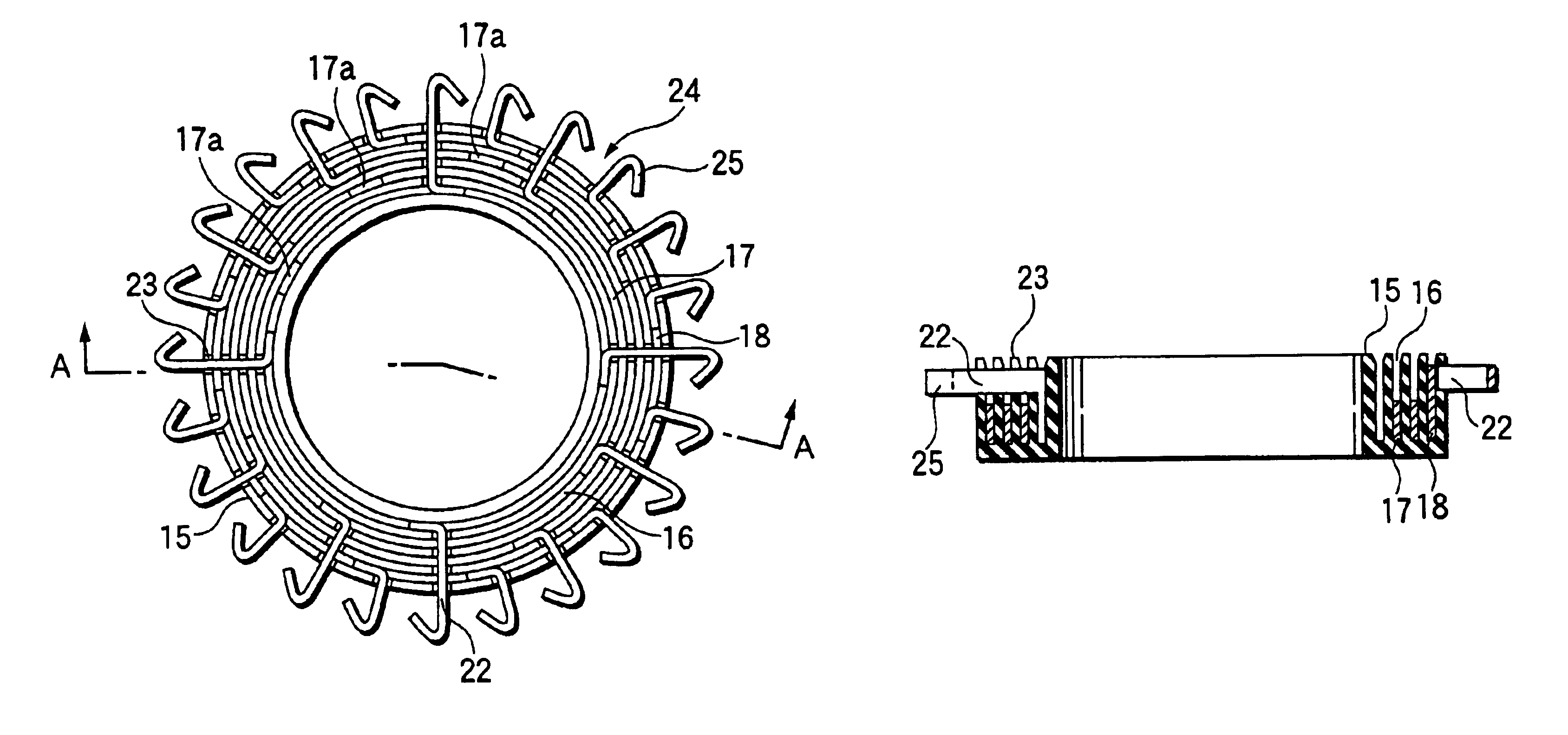
[0062]FIG. 4A is a front view of a coil connector, and FIG. 4B is a cross-sectional view of the coil connector, taken along the line A—A. FIG. 5A is a front view of a holder, and FIG. 5B is a cross-sectional view of the holder, taken along the line B—B. FIGS. 6A, 6B and 6C are front views of a split phase conductive member, and FIG. 6D is a front view of a common conductive member. FIG. 7A is an expanded view of the split phase conductive member, and FIG. 7B is an expanded view of the common conductive member. The same or like parts are designated by the same numerals throughout the drawings. In FIG. 1, 1 denotes...

embodiment 2

(Embodiment 2)

[0071]Referring to FIGS. 8 and 9, an embodiment 2 of this invention will be described below. FIG. 8 is a front view of an in-phase split phase conductive member. FIG. 9 is an expanded view of the in-phase split phase conductive member. In the embodiment 1, the split phase conductive member 17 as shown in FIG. 7A and FIGS. 6A to 6C has four arm portions 22 for each split phase conductive member, and the connection terminal 17a is a separate component, and joined by welding. However, in the embodiment 2, the split phase conductive member 17 is divided into two pieces as shown in FIGS. 9A and 9B, each piece having two arm portions 22. The connection terminal 17a is formed integrally, as shown in FIG. 9C, by bending an end portion of each strip conductive portion 24 of FIGS. 9A and 9B within the same plane. In this way, two split phase conductive members 17 of FIG. 8A are formed from the conductive members as shown in FIGS. 9A and 9B, and combined as shown in FIG. 8B to pr...

embodiment 3

(Embodiment 3)

[0073]Referring to FIG. 10, an embodiment 3 of this invention will be described below. FIG. 10A is an expanded view of the split phase conductive member, and FIG. 10B is a perspective view showing a state where both the end portions of the strip conductive portion 24 are bent within the same plane and butted. In FIG. 10A, the split phase conductive member 17, like that as shown in FIG. 7A and FIG. 6A, has four arm portions 22. Though in the embodiment 1, the connection terminal 17a is a separate component and joined by welding, in the embodiment 3 both the end portions of the strip conductive portion 24 of FIG. 10A are bent within the same plane and butted, as shown in FIG. 10B. As in the embodiment 2, there is a smaller clearance 26 between the side end portion 24a of the strip conductive portion 24 and the arm portion 22, in which the arm portion 22 is formed by lancing with press.

[0074]In the embodiment 3 as constituted in this manner, the connection terminals 17a a...


PUM


Abstract

A conductive member includes a strip conductive portion 24 and an arm portion 22 integral with the strip conductive portion 24 and extending from a side end portion 24a of the strip conductive portion 24 to be almost parallel in a longitudinal direction, the arm portion being bent in a direction of plate thickness for the strip conductive portion 24.

Description

BACKGROUND OF THE INVENTION[0001]1. Field of the Invention[0002]The present invention relates to a rotating electric machine and a method for manufacturing the same, and more particularly to a coil connecting structure.[0003]2. Related Art[0004]The conventional device with a coil connecting structure for a rotating electric machine was disclosed in the Unexamined Japanese Patent Application Publication Nos. Hei11-18345 and 2000-333400, for example. Firstly, in the Unexamined Japanese Patent Application Publication No. Hei11-18345, a conductive member is formed like a strip from a conductive material and has a plurality of terminal pieces on the side face, each terminal piece being jutted through an insertion hole and bent outwards. Also, the terminal piece has a U-character groove on the side face of the strip conductor, and the stator winding has its start end and terminal end fitted into this groove and soldered. Secondly, in the Unexamined Japanese Patent Application Publication ...

Claims


Application Information

Patent Timeline
Patent Type & Authority Patents(United States)
IPC IPC(8): H02K3/52H02K3/50H02K3/46H02K3/04H02K15/04
CPCH02K3/50H02K3/522H02K2203/09
Inventor YAMAMURA, AKIHIROTAKAKI, TETSUNAOTAKAHASHI, TSUYOSHIMIYAKE, AKIFUMIIZAWA, AKIRANONOGUCHI, HIROMUMATSUNAGA, KAZUOAKITA, HIROYUKI
Owner MITSUBISHI ELECTRIC CORP
Why Eureka
Try Eureka