Electronic ballast for a high-pressure discharge lamp

a technology of high-pressure discharge and electronic ballast, which is applied in the direction of electric variable regulation, process and machine control, instruments, etc., can solve the problem of not being able to apply the art disclosed to the hid lamps

Inactive Publication Date: 2005-07-05
MATSUSHITA ELECTRIC WORKS LTD
View PDF11 Cites 59 Cited by
  • Summary
  • Abstract
  • Description
  • Claims
  • Application Information

AI Technical Summary

Benefits of technology

[0022]Color temperatures or color (chromaticity) deviations may be used as lamp output parameters for lamp discrimination. An HID lamp exhibits a different color temperature and a different color deviation when it is lit with the ballast output power equal to its rated power than when it is lit with a higher or lower ballast output power. To this end, the lamp power switching means includes a color temperature monitor or a color deviation monitor. The memory stores data on the color temperatures or color deviations that HID lamps having different rated powers exhibit when they are lit with different ballast output powers. The lamp discriminator compares the detected color temperature or color deviation with the data in the memory so as to discriminate the rated power of the HID lamp connected to the ballast. This makes it possible to provide a ballast output power adequate to the rated lamp power.

Problems solved by technology

This makes it impossible to apply to the HID lamps the art disclosed by the foregoing publication.

Method used


Image

  • Electronic ballast for a high-pressure discharge lamp
  • Electronic ballast for a high-pressure discharge lamp
  • Electronic ballast for a high-pressure discharge lamp

Examples


first embodiment

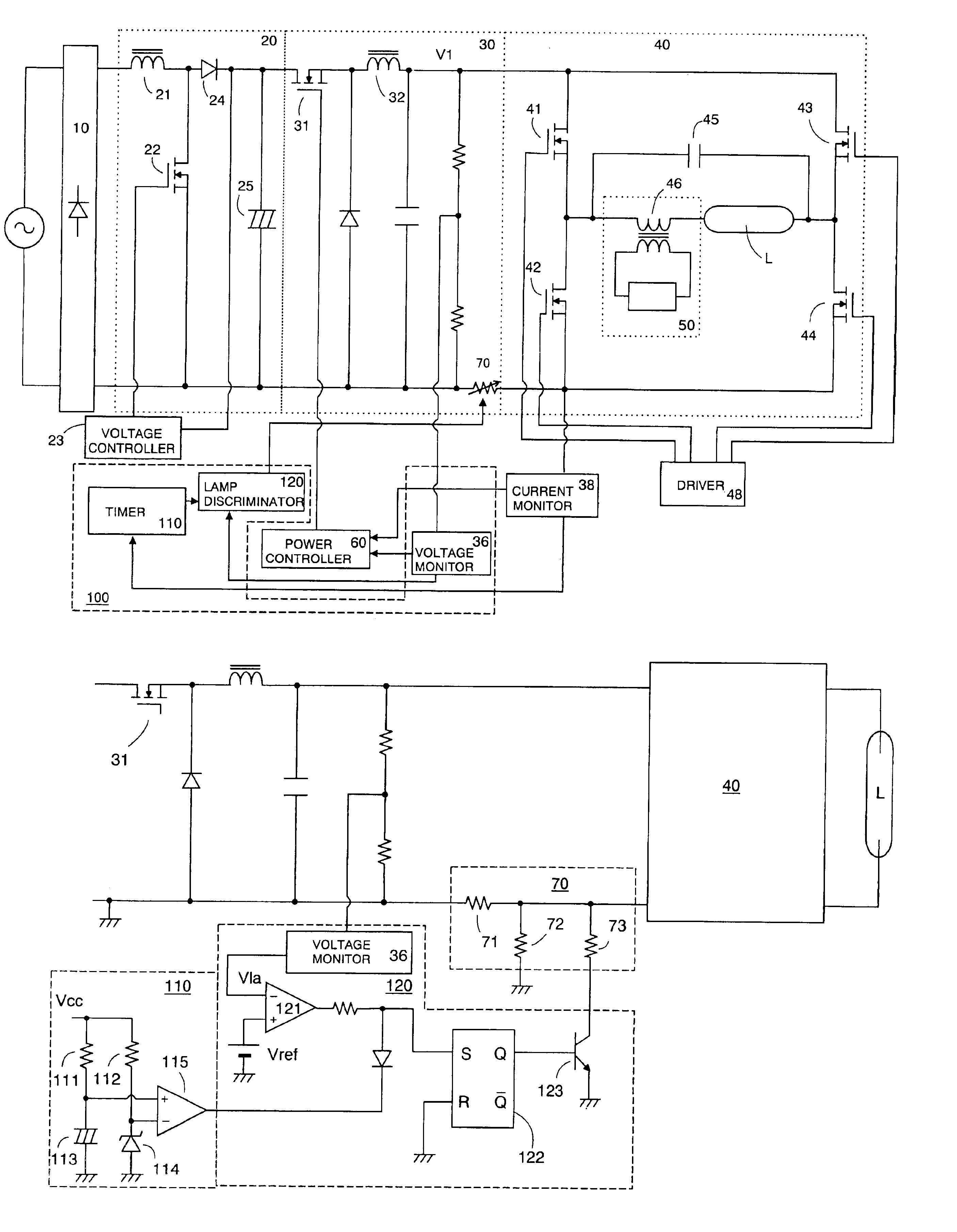
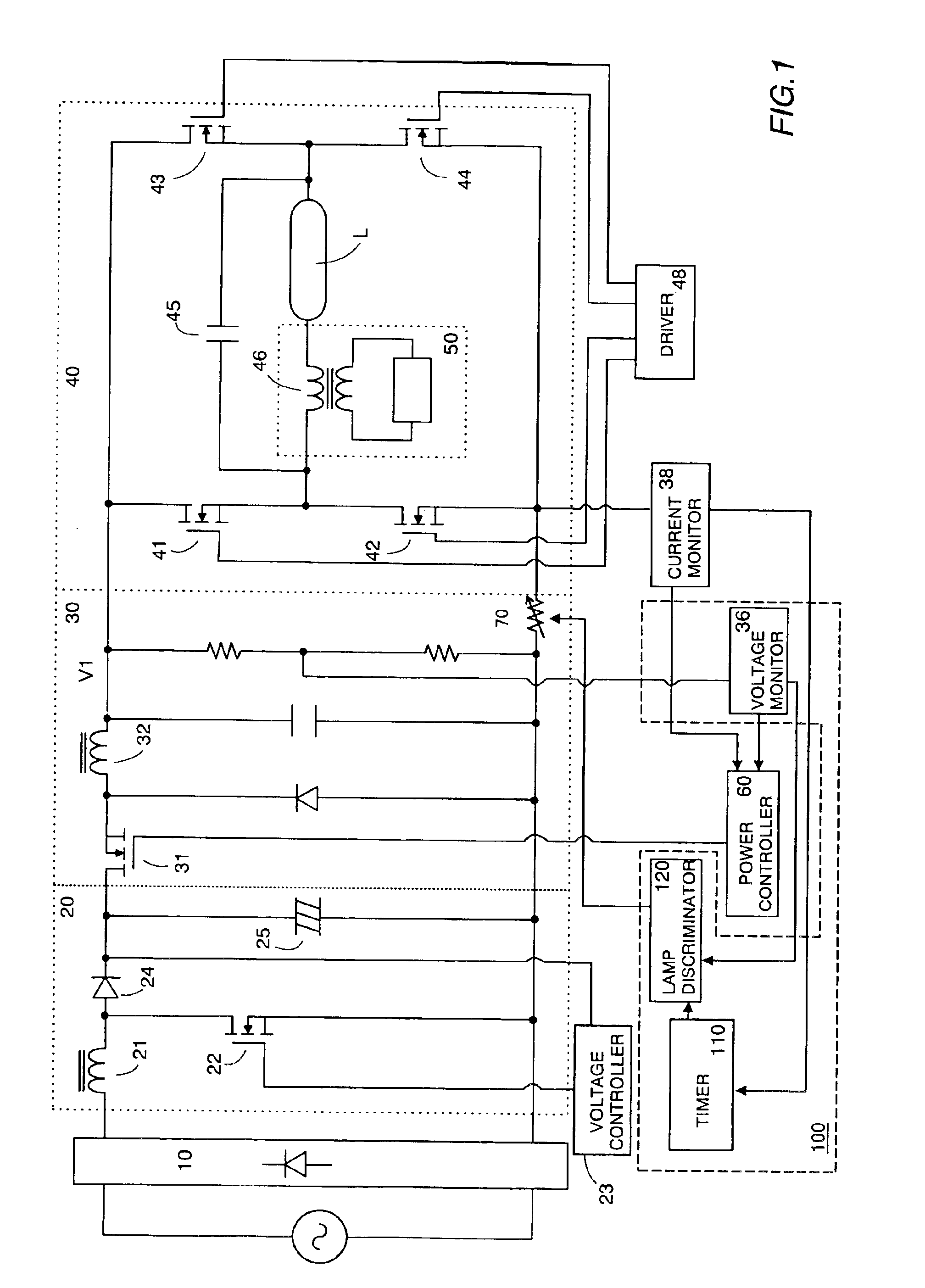
[0036]FIG. 1 shows an electronic ballast for a high intensity discharge lamp according to the present invention, which may be a metal halide lamp. The ballast includes a rectifier 10, a step-up chopper 20, a step-down chopper 30, an inverter 40 and an igniter 50. The rectifier 10 is connected to an AC power supply and provides a rectified DC voltage. The step-up chopper 20 boosts the rectified DC voltage. The step-down chopper 30 decreases the boosted DC voltage and provides a control DC voltage. The inverter 40 converts the control DC voltage into a rectangular-wave AC voltage and applies the AC voltage to the HID lamp L. The igniter 50 ignites the HID lamp L. The step-up chopper 20 includes an inductor 21 and a transistor switch 22, which are connected in series to both ends of the rectifier 10. The transistor switch 22 is a MOSFET, which is turned on or off by a voltage controller 23 at a high frequency and accumulates a smooth voltage through a diode 24 in a smoothing capacitor ...

fourth embodiment

[0061]FIG. 10 shows a ballast for a high intensity discharge lamp according to the present invention. This embodiment is identical with the embodiment shown in FIG. 9 except that, in this embodiment, the lamp power switching means 200 includes an aging monitor 260 in place of the rest counter. The aging monitor 260 monitors the lamp voltage Vla of the HID lamp to monitor the variation of a lamp characteristic of the lamp with the lamp aging. As an HID lamp is used for a long time, its lamp voltage Vla tends to rise. This embodiment makes it possible to accurately discriminate the rated power of an HID lamp even if the lamp voltage Vla of the lamp varies as the lamp is used for a long time. The aging monitor 260 sends the lamp discriminator 220 a signal indicative of the cumulative using time of the HID lamp L. On the basis of the cumulative using time, the lamp discriminator 220 corrects the accumulated time period and / or the reference time. With regard to the amount of correction, ...

fifth embodiment

[0063]FIG. 11 shows a ballast for a high intensity discharge lamp according to the present invention. As is the case with the embodiment shown in FIG. 10, this ballast includes a microprocessor 330, into which the current monitor 38, the voltage monitor 36 and the power controller 60 are incorporated in addition to a lamp power switching means 300. The lamp power switching means 300 differs from the counterpart(s) of the foregoing embodiment(s) in discriminating the lamp power on the basis of the lamp voltage Vla exhibited after the HID lamp L reaches its stable lamp operating condition. In general, even if HID lamps have different rated powers, they exhibit nearly equal rated voltages when they are lit stably at their respective rated powers. However, if the rated power of each of the HID lamps differs from the ballast output power, as is the case before the lamp is stably lit, the lamp voltage Vla differs from the rated lamp voltage even after the lamp is lit stably. This embodime...


PUM


Abstract

An electronic ballast for a high intensity discharge lamp (HID) includes a power converters, a controller, and a lamp power switch. In the power converter, an input DC voltage is converted into a ballast output power for lighting the HID lamp. The controller has a function to control the power converter and change the ballast output power. The lamp power switch detects a lamp output parameter indicated after the HID lamp starts discharge, identifies a lamp power of the HID lamp according to the lamp output parameter, and gives an identification signal indicating the lamp power. In response to this identification signal, the power converter outputs the ballast output power which matches with the lamp power identified.

Description

BACKGROUND OF THE INVENTION[0001]1. Field of the Invention[0002]The present invention relates to an electronic ballast for a high intensity discharge lamp. More specifically, the invention relates to an electronic ballast for a high intensity discharge lamp that enables high intensity discharge lamps having different rated powers to be lit according to the rated powers.[0003]2. Description of the Prior Art[0004]Japanese Patent Publication H7-66864 discloses a ballast for lighting two or more fluorescent lamps having different rated powers. The ballast is so designed as to determine the rated power of a fluorescent lamp by taking advantage of the fact that different starting voltages are applied to start fluorescent lamps having different rated powers. In addition, the ballast is so designed as to supply a current according to the determined power. In other words, the ballast determines the rated powers of fluorescent lamps from the difference among the starting voltages applied to s...

Claims


Application Information

Patent Timeline
Patent Type & Authority Patents(United States)
IPC IPC(8): H05B41/38H05B41/28H05B41/36H05B41/288
CPCH05B41/2882H05B41/2887H05B41/36H05B41/38H05B41/388Y02B20/202Y02B20/204Y02B20/00
Inventor YAMAUCHI, TOKUSHISHIOMI, TSUTOMUMAEHARA, MINORUIWAHORI, YUTAKANAKAMURA, TOSHIAKIKAMOI, TAKESHI
Owner MATSUSHITA ELECTRIC WORKS LTD
Why Eureka
Try Eureka