
Cooling device for battery pack and rechargeable battery

a battery pack and cooling device technology, applied in the direction of secondary cell servicing/maintenance, cell components, sustainable manufacturing/processing, etc., can solve the problems of inability to reduce space, adversely increase the cost, and affect the cooling efficiency, so as to reduce the cost, reduce the cost, and efficiently and uniformly cool the battery.

Inactive Publication Date: 2005-07-05
PANASONIC CORP +1
View PDF5 Cites 25 Cited by
  • Summary
  • Abstract
  • Description
  • Claims
  • Application Information

AI Technical Summary

Benefits of technology

[0013]In light of the above conventional problems, the present invention has an object of providing a cooling device for a battery pack and a rechargeable battery, which allow the battery pack to be efficiently and uniformly cooled while achieving the reduction in cost as well as in space, enabling the accurate control of a battery temperature.
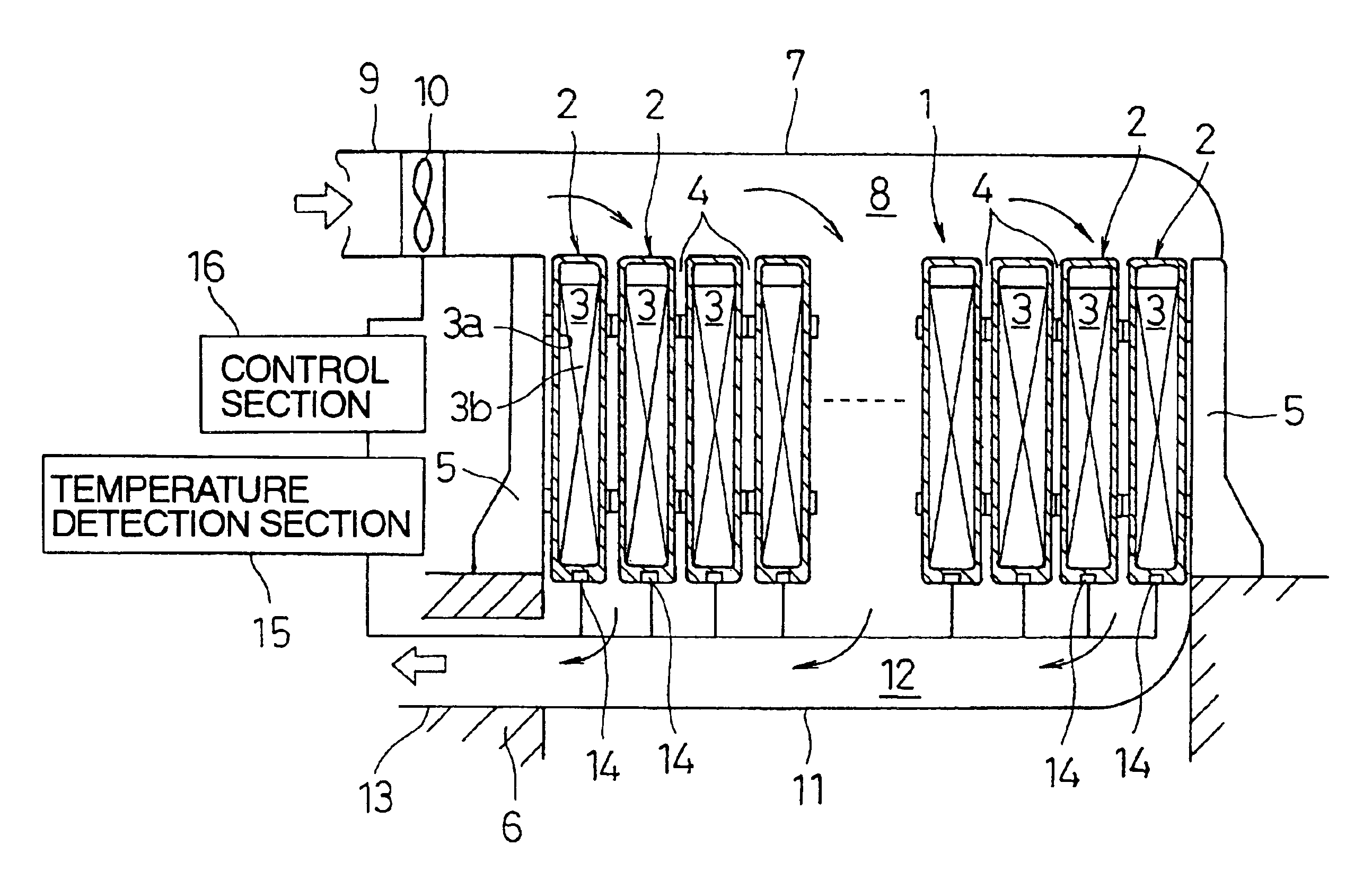
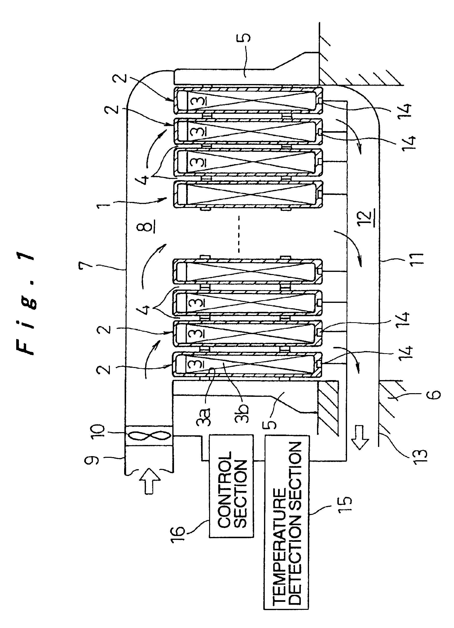
[0015]According to such a structure, since cooling air is downwardly sent from above the battery pack through the ventilation space between the rechargeable batteries, an upper part of each of the rechargeable batteries where heat generating portions concentrate is first cooled to efficiently cool the battery pack as a whole as well as to restrain a variation in temperature between the upper part and a lower part of the rechargeable battery. Although the lower end of the rechargeable battery has the highest temperature as a result of cooling in a downflow system, since the temperature of the lower end of the rechargeable battery is detected by the temperature detection sensor to control the blower device, a temperature of the entire battery pack is regulated to be within an appropriate range so as to prevent a decrease in a battery output, charging / discharging efficiency, and battery service life. Furthermore, since the downflow system is employed, an air duct for cooling air is simplified in a case where air is taken from a vehicle compartment so as to be sent as cooling air, thereby reducing the cost and the space.
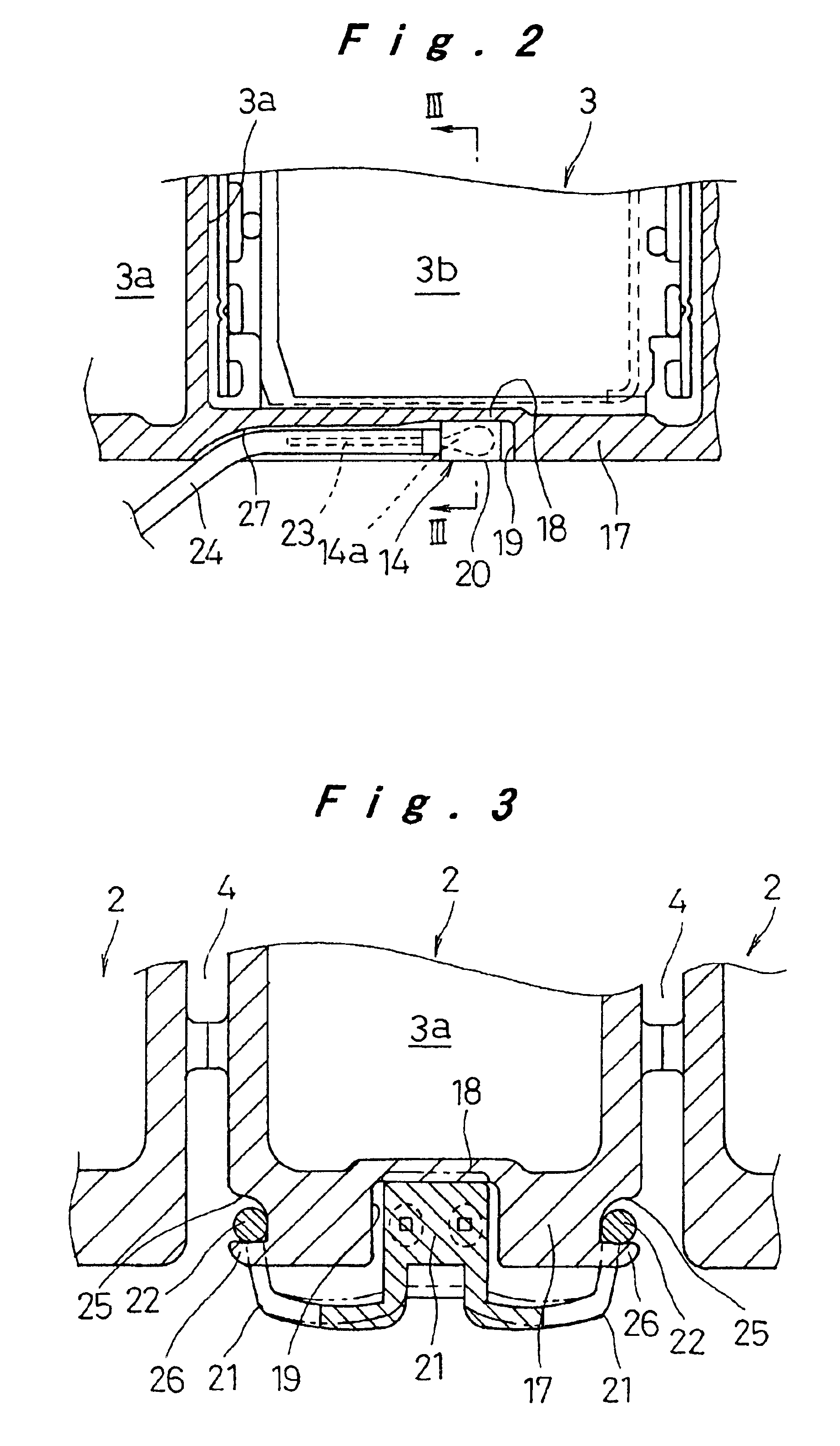
[0016]In a rechargeable battery according to the present invention, including an electricity generating element housed in a sealed prismatic battery case, a sensor placement concave is provided on a bottom wall of the battery case through a partition wall thinner than the bottom wall so as to be separated from a space within the battery case. The temperature detection sensor is provided in the sensor placement concave so as to be pressed against the partition wall. A temperature of the lower end of the rechargeable battery, which has the highest temperature in a case where the battery pack is cooled in a downflow system, is thereby detected. Moreover, since the temperature detection sensor is pressed against the thin partition wall, a temperature inside the battery case is detected with good accuracy and good response.

Problems solved by technology

Consequently, the upflow system is disadvantageous in that cooling efficiency is impaired because a portion having a higher temperature is cooled with cooling air having the lowered cooling capacity and that a variation in temperature between the upper part and the lower part of the rechargeable battery 32 is increased.
As a result, the cost is adversely increased, and the space cannot be reduced due to the provision of the air duct 40.

Method used


Image

  • Cooling device for battery pack and rechargeable battery
  • Cooling device for battery pack and rechargeable battery
  • Cooling device for battery pack and rechargeable battery

Examples


Embodiment Construction

[0027]Hereinafter, an embodiment of a cooling device for a battery pack and a rechargeable battery constituting the battery pack according to the present invention will be described with reference to FIGS. 1 to 7.

[0028]In FIG. 1, reference numeral 1 denotes a battery pack serving as a power source for electric vehicles including hybrid cars. In the battery pack 1, twenty to thirty rechargeable batteries 2 are arranged in parallel with ventilation spaces 4 being provided between the respective rechargeable batteries 2. The rechargeable batteries 2 are interposed between a pair of end plates 5 provided on both, ends of the rechargeable batteries 2 so as to be integrally fixed therebetween, thereby constituting the battery pack 1.

[0029]Each of the rechargeable batteries 2 is constituted as a battery module that is formed by arranging a plurality of cells 3 in parallel in an integrated manner and internally connecting these cells in series. Each of the cells 3 is constituted by housing ...


PUM


Abstract

In a battery pack including a plurality of prismatic rechargeable batteries arranged in parallel with ventilation spaces being provided therebetween, the battery pack is constituted so that cooling air is downwardly sent from above the battery pack through the ventilation spaces. In accordance with a temperature detected with a temperature detection sensor attached to the lower end of the rechargeable battery, a blower fan is controlled by a control section. Moreover, a sensor placement concave, which is separated from a space inside a battery case through a thin partition wall, is provided on a bottom wall of the battery case of the rechargeable battery. The temperature detection sensor is placed in the sensor placement concave so as to be pressed against the partition wall.

Description

[0001]The present disclosure relates to subject matter contained in priority Japanese Patent Application No. 2002-148009, filed on May 22, 2002, the contents of which is herein expressly incorporated by reference in its entirety.BACKGROUND OF THE INVENTION[0002]1. Field of the Invention[0003]The present invention relates to a cooling device for a battery pack including a plurality of prismatic rechargeable batteries that are arranged in parallel and to such a rechargeable battery.[0004]2. Description of Related Art[0005]In a conventional battery pack, in order to prevent decrease in a battery output, charging / discharging efficiency, and battery service life due to the elevation of the battery temperature by heat generation that occurs along with charging / discharging, for example, a fan is provided to send cooling air between cells in the battery pack or between battery modules, each including a plurality of serially connected cells.[0006]The above-mentioned structure will be describ...

Claims


Application Information

Patent Timeline
IPC IPC(8): H01M10/46H01M10/42H02J7/00H01M2/02H01M10/50H01M10/04H01M10/60H01M10/613H01M10/617H01M10/625H01M10/633H01M10/647H01M10/6563H01M50/209H01M50/569
CPCH01M2/1016H01M2/1061H01M10/425H01M10/486H01M10/5004H01M10/5016H01M10/5032H01M10/5059H01M10/5067H01M10/625H01M10/6563H01M10/647H01M10/6557H01M10/613Y02E60/10H01M50/209Y02P70/50H01M50/569
Inventor HAMADA, SHINJIASAHINA, TAKASHIETO, TOYOHIKOWATANABE, KO
Owner PANASONIC CORP
Learn More