

Optical module and method of manufacturing the same, and optical transmission device
a technology of optical modules and optical transmission devices, which is applied in the direction of optical elements, semiconductor lasers, instruments, etc., can solve the problems of difficult handling of optical fibers, difficulty in alignment between optical devices and optical fibers, and difficulty in alignment with accuracy
- Summary
- Abstract
- Description
- Claims
- Application Information
AI Technical Summary
Problems solved by technology
Method used
Image

Examples
first embodiment
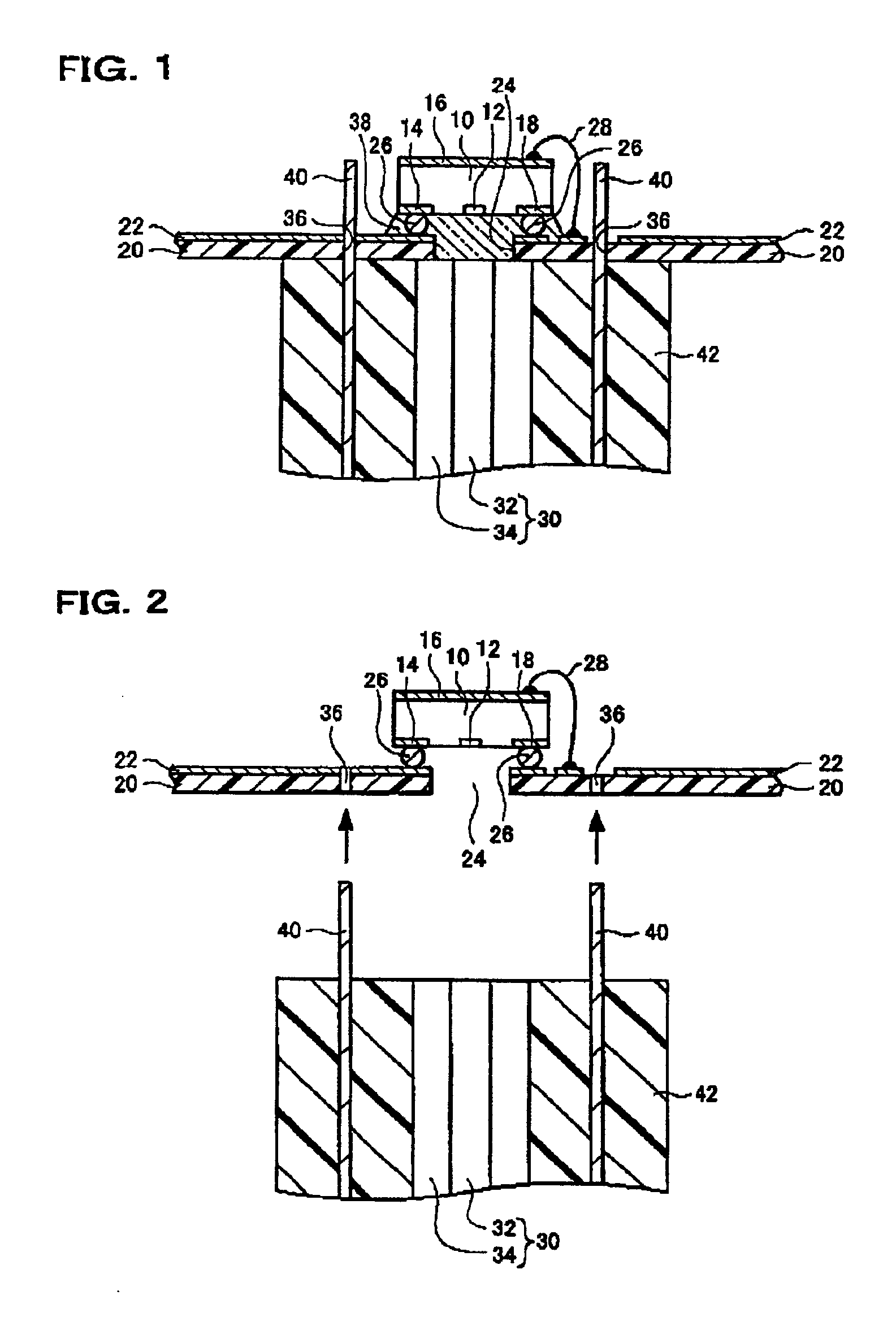
[0100]FIGS. 1 and 2 show an optical module according to a first embodiment to which the present invention is applied and a method of manufacturing the same. The optical module includes an optical device 10, a substrate 20 and an optical fiber 30. The optical fiber 30 has a guide at an end portion thereof. In this embodiment, the guide is a pin 40. Note that the optical fiber 30 is an example of an optical waveguide.
[0101]The optical device 10 may be a light-emitting or light-receiving device. The light-emitting device is to be applied, as an example, by a surface-emitting device, particularly a surface-emitting laser. The surface-emitting device, such as a surface-emitting laser, emits light in a direction perpendicular to the substrate. The optical device 10 has an optical part 12. When the optical device 10 is a light-emitting device, the optical part 12 is a light emitting part while, when the optical device 10 is a light-receiving device, the optical part 12 is a light-receiving...
second embodiment
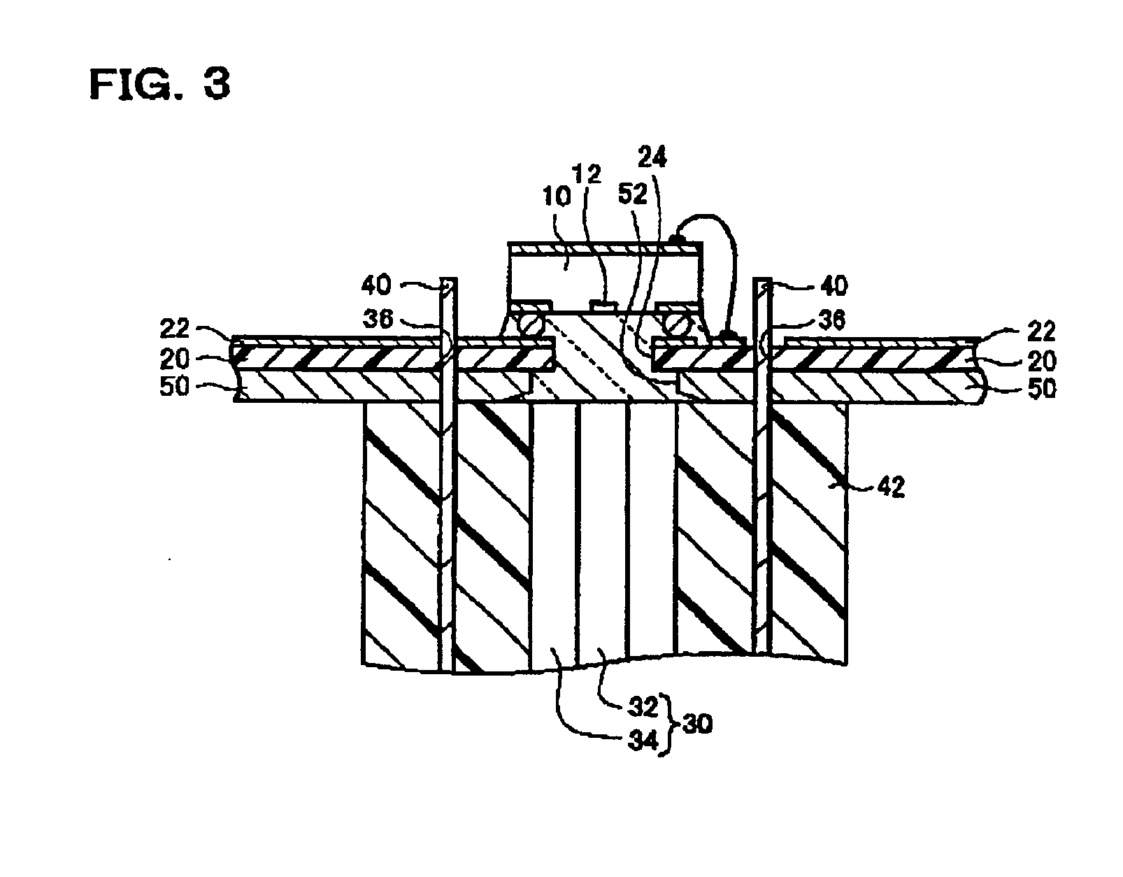
[0128]FIG. 3 shows an optical module according to a second embodiment to which the invention is applied. For the example shown below, the explanation to be made in other embodiments is applicable to a possible extent. Note that the duplicated explanations with respect to the foregoing embodiment are omitted in this embodiment.
[0129]This optical module further includes a support member 50 provided on the substrate 20. The support member 50 is provided on the surface of substrate 20 opposite to the surface mounting the optical device 10. The support member 50 is provided in a part or the entire of the substrate 20. The shape may be nearly in an equal form to the planar shape of the substrate 20. The support member 50 may be formed with an aperture 52 communicating with the aperture 24 of the substrate 20. Namely, an optical path is secured between the end surface of optical module 30 and the optical part 12 by the aperture 24 of substrate 20 and the aperture 52 of support member 50.
[0...
third embodiment
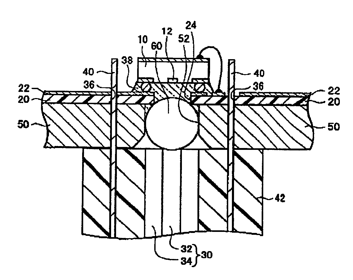
[0135]FIG. 4 shows an optical module according to a third embodiment to which the invention is applied. For the example shown below, the explanation to be made in other embodiments is, applicable to a possible extent.
[0136]This optical module further includes a lens 60. The lens 60 is provided between the optical part 12 of optical device 10 and the end surface of optical fiber 30. The lens 60 may be adhered to the optical device 10 and substrate 20 by light-transmissive resin 38.
[0137]The lens 60 is used to make the light-intensity distribution equal between the optical part 12 and the core 32 of optical fiber 30. In particular, in the case a plastic fiber is used as an optical fiber 30, the lens 60 may be provided on a side close to the light-receiving device because of large diameter of the core 32.
[0138]Where a support member 50 is provided on the substrate 20, the lens 60 may be placed in an aperture 52 of the support member 50. For example, where the lens 60 is spherical, an a...
PUM
 Abstract
Description
Claims
Application Information