
Apparatus for contracting, loading or crimping self-expanding and balloon expandable stent devices

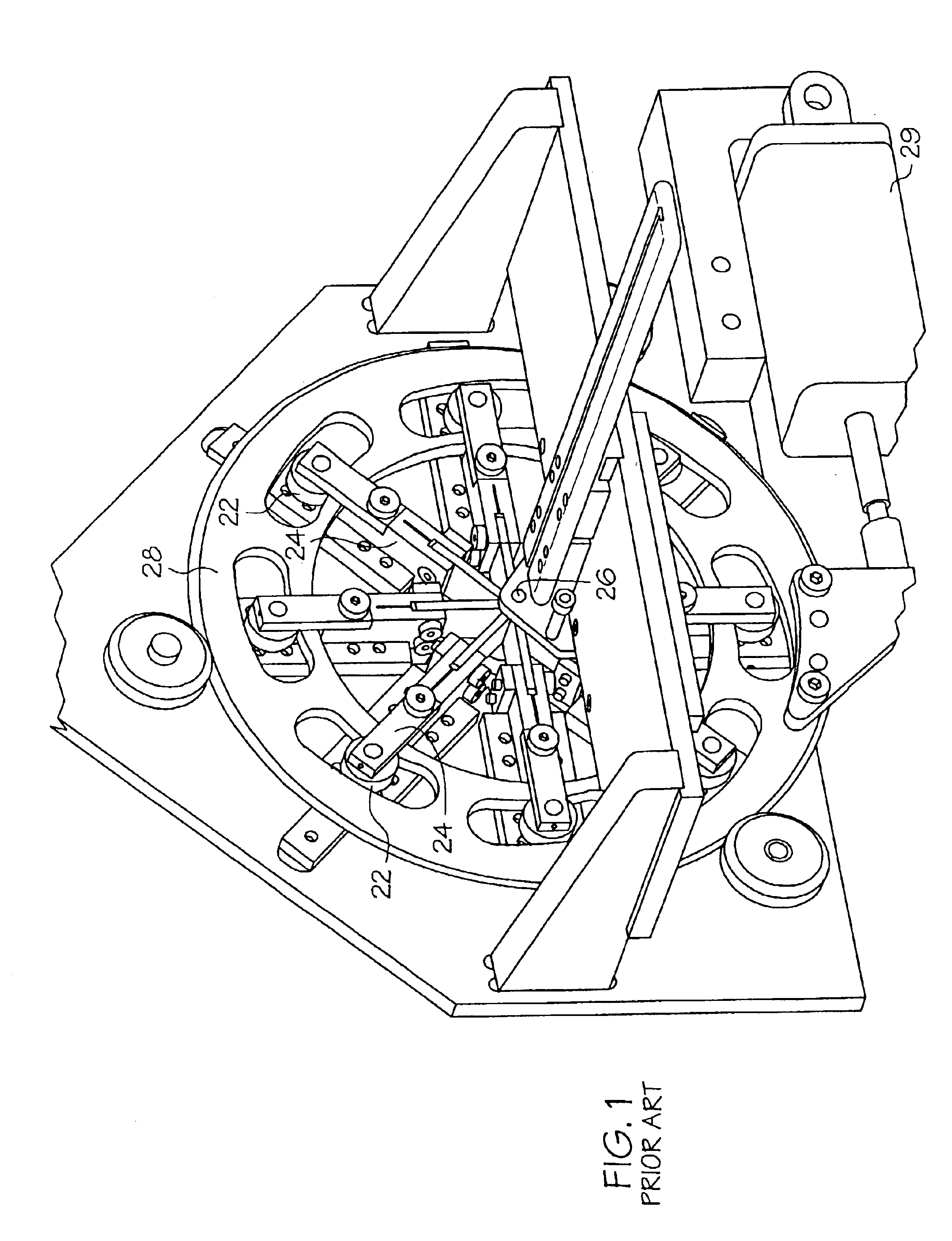
a technology of self-expanding and balloons, which is applied in the direction of forging/pressing/hammering apparatus, prosthesis, blood vessels, etc., can solve the problems of stents that are not properly secured or retained to the catheter, slipping, and being deployed in the wrong location, etc., to minimize the distortion of score and mark

Inactive Publication Date: 2005-07-12
BOSTON SCI SCIMED INC +2
View PDF104 Cites 97 Cited by
  • Summary
  • Abstract
  • Description
  • Claims
  • Application Information

AI Technical Summary

Benefits of technology

The present invention is about a device and method for crimping medical devices, such as stents, to a smaller size while minimizing distortion and scoring. The invention includes a device with movable blades that can be controlled to change the size of an aperture through which a medical device is placed. The blades have a single point on the surface of a reference circle or a radius of a reference tube, and they can be moved inward to apply a radial force to the medical device. The invention also includes a method for molding a medical balloon by using a shrinkable tubular aperture formed by the movable blades. The technical effects of the invention include the ability to crimp medical devices to a smaller size with minimal distortion and scoring, and the ability to mold medical balloons with precision.

Problems solved by technology

Stents that are not properly secured or retained to the catheter may slip and either be lost or be deployed in the wrong location.
In the past, this crimping or size reduction has been done by hand often resulting in the application of undesired uneven forces to the stent.
Stents which have been crimped or otherwise reduced in size multiple times can suffer from fatigue and may be scored or otherwise marked which can cause thrombosis.
A poorly crimped stent can also damage the underlying balloon.

Method used


Image

  • Apparatus for contracting, loading or crimping self-expanding and balloon expandable stent devices
  • Apparatus for contracting, loading or crimping self-expanding and balloon expandable stent devices
  • Apparatus for contracting, loading or crimping self-expanding and balloon expandable stent devices

Examples


Embodiment Construction

[0042]While this invention may be embodied in many different forms, there are described in detail herein specific preferred embodiments of the invention. This description is an exemplification of the principles of the invention and is not intended to limit the invention to the particular embodiments illustrated.

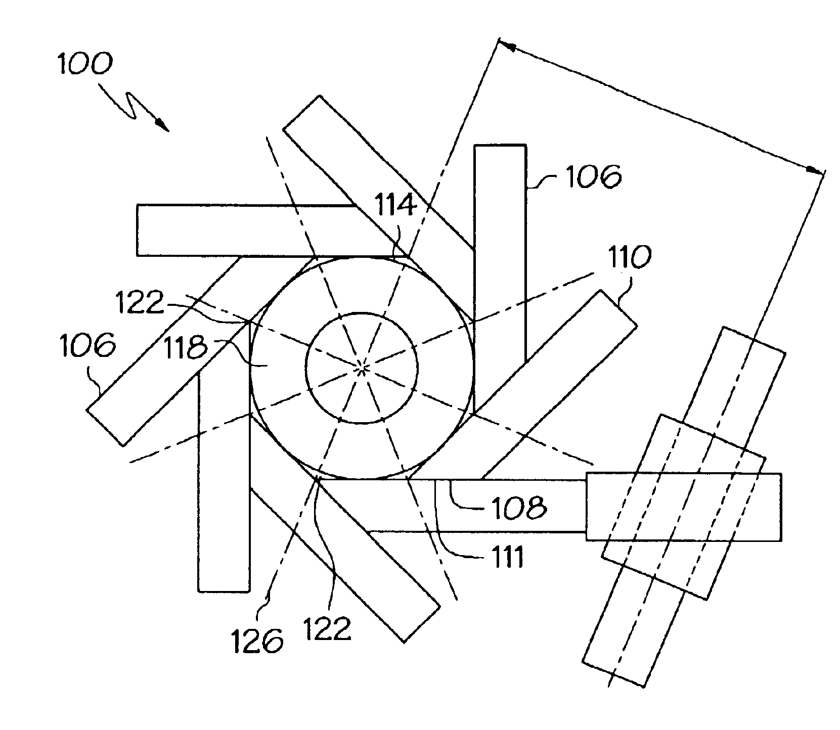
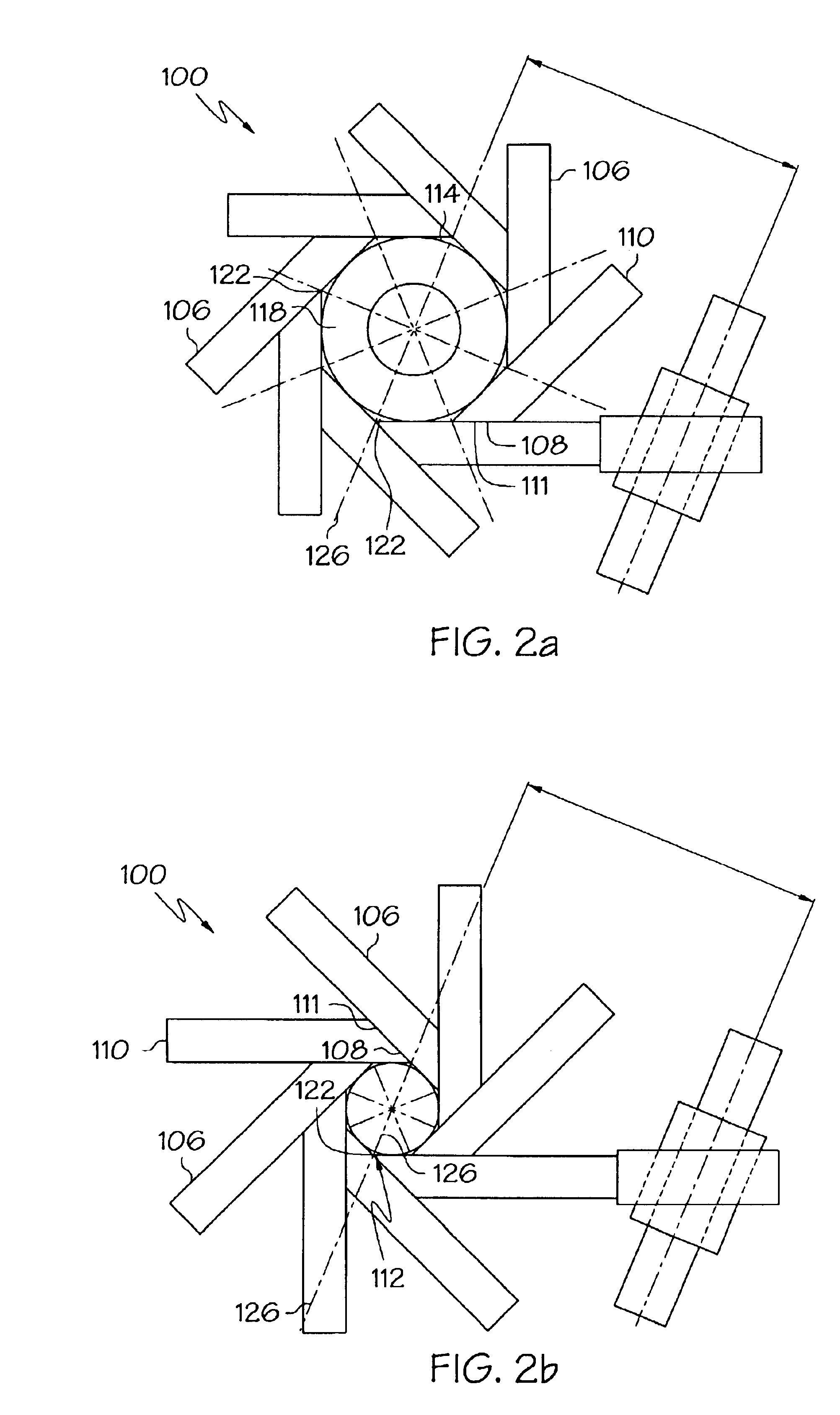
[0043]As shown generally at 100 in FIGS. 2a and 2b, the inventive apparatus comprises eight coupled blades 106 disposed about a reference circle 114 to form an aperture 118 whose size may be varied. The apparatus may comprise as few as three blades and as many as sixteen or more blades. Desirably, the apparatus will have four or more blades and more desirably, eight or more blades. The maximum number of blades is limited only by how many blades can physically be coupled together under the relevant size constraints. As the number of blades is increased, the profile of the aperture and hence of the medical device following reduction in size, becomes smoother. FIG. 2b shows the ...


PUM

PropertyMeasurementUnit
sizeaaaaaaaaaa
temperatureaaaaaaaaaa
lengthaaaaaaaaaa

Abstract

An apparatus for manipulating a medical device is formed of at least three coupled movable blades which are disposed about a reference circle to form an aperture whose size may be varied. The aperture capable of being sized to contain a medical device. Each blade is in communication with an actuation device which is capable of moving the blade to alter the size of the aperture. Each blade includes a single radial point which a) lies on the circumference of the reference circle prior to movement of the blade, and b) may be moved only along a radius of the reference circle on movement of the blade.

Description

CROSS-REFERENCE TO RELATED APPLICATIONS[0001]This application is a Continuation application from application Ser. No. 09 / 966,686 filed Oct. 1, 2001 now U.S. Pat. No. 6,823,576 which is a Continuation application from application Ser. No. 09 / 401,218 filed Sep. 22, 1999, now U.S. Pat. No. 6,360,577, issued Mar. 26, 2002 the contents of which are hereby incorporated by reference.BACKGROUND OF THE INVENTION[0002]This invention relates to an apparatus and a method for reducing in size a medical device such as a stent, stent-graft, graft, or vena cava filter. The apparatus may be used in particular for fastening a medical device onto a catheter.[0003]Medical devices such as stents, stent-grafts, grafts, or vena cava filters and catheters for their delivery are utilized in a number of medical procedures and situations, and as such their structure and function are well known.[0004]A stent, for example, is a generally cylindrical prosthesis introduced via a catheter into a lumen of a body ve...

Claims


Application Information

Patent Timeline
Patent Type & Authority Patents(United States)
IPC IPC(8): A61F2/06A61F2/84
CPCA61F2/95A61M25/1029A61F2/958Y10T29/53717A61F2002/9522Y10T29/49865Y10T29/53096Y10T29/5367Y10T29/4981Y10T29/53987Y10T29/49913Y10T29/49908Y10T29/49927Y10T29/53996Y10T29/49925A61F2/9522A61F2/9524
Inventor AUSTIN, MICHAEL
Owner BOSTON SCI SCIMED INC
Learn More