
Dual fuel fin mixer secondary fuel nozzle

a technology of fuel nozzle and mixer, which is applied in the direction of engine ignition, engine starter, lighting and heating apparatus, etc., can solve the problems of high nitrogen oxide emissions of pilot flames and high emissions of diffusion type nozzles, and achieve the effect of reducing nox and other air pollutants

Inactive Publication Date: 2005-07-12
ANSALDO ENERGIA SWITZERLAND AG
View PDF17 Cites 67 Cited by
  • Summary
  • Abstract
  • Description
  • Claims
  • Application Information

AI Technical Summary

Benefits of technology

The present invention provides a fuel nozzle for a gas turbine engine that reduces NOx and other air pollutants during gas operation. It also provides a premixed fuel nozzle with an injector assembly comprising a plurality of radially extending fins to inject fuel and air into the combustor such that the fuel and air premixes, resulting in a more uniform injection profile for improved combustor performance. Additionally, it provides an enriched fuel air shear layer to enhance combustor lean blowout margin in the downstream flame zone. The fuel nozzle is premixed when operating on gaseous fuel and has the additional capability of operating on liquid fuel. It also provides improved combustion stability through the use of a plurality of fuel injection orifices located along a conical surface of the premixed fuel nozzle. The invention also includes an alternate embodiment comprising a plurality of radially extending fins to inject fuel only, wherein the nozzle body is configured to reduce blockage between adjacent fins and has the additional capability of operating on liquid fuel.

Problems solved by technology

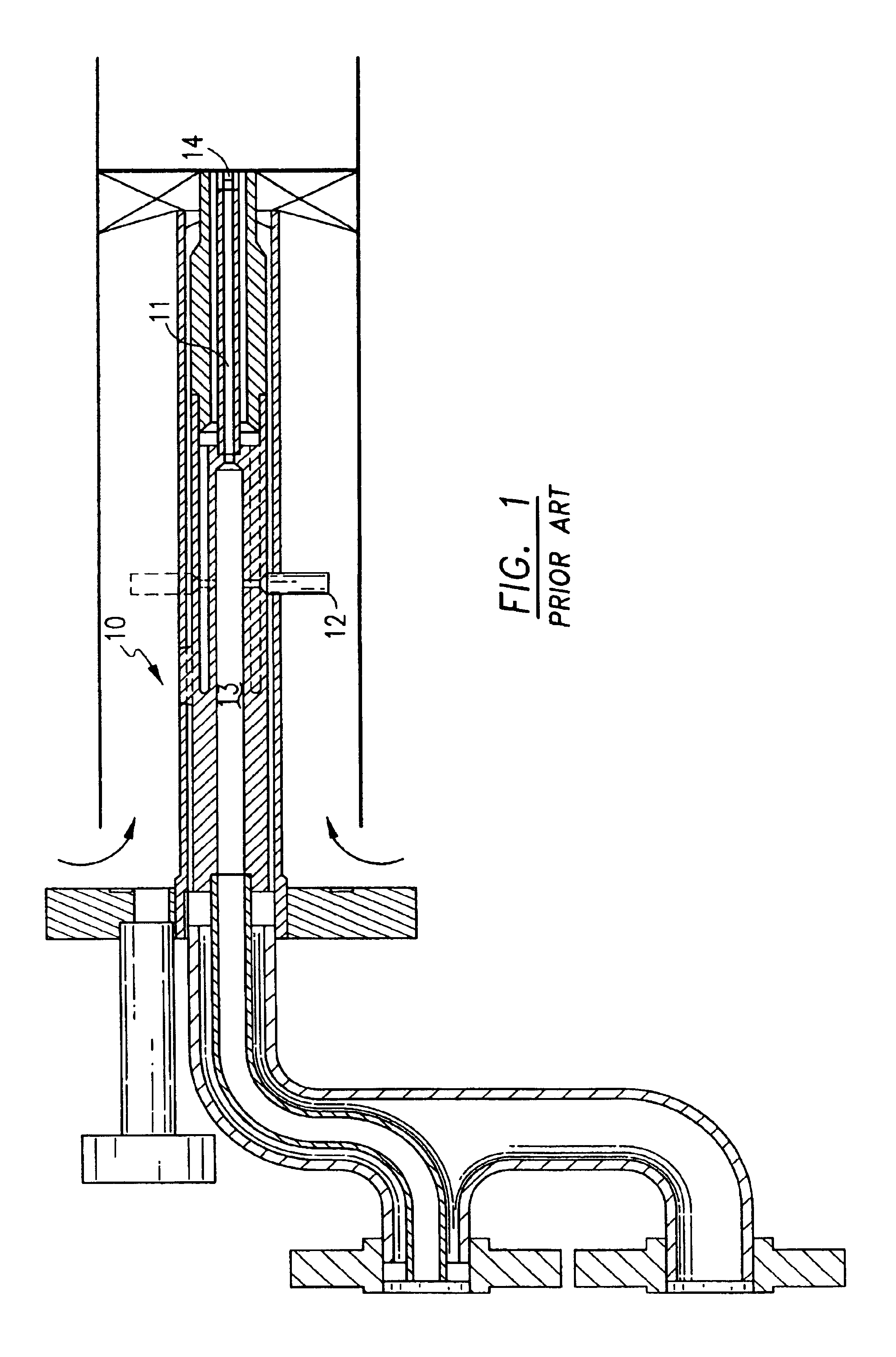
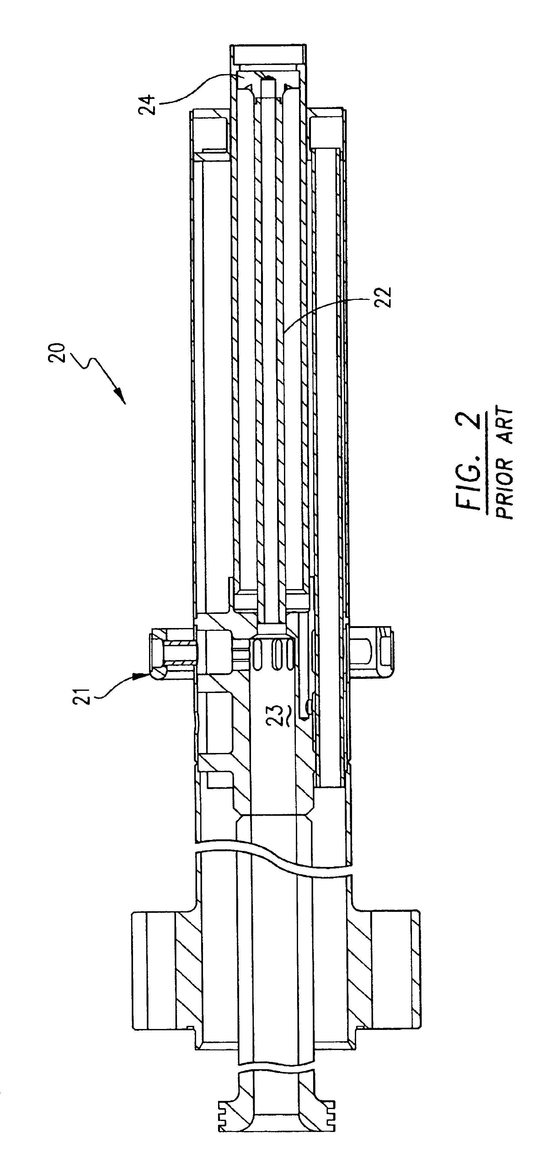
Diffusion type nozzles produce high emissions due to the fact that the fuel and air burn stoichiometrically at high temperature.
Though this pilot flame is stable, it is extremely fuel rich and upon combustion with compressed air, this pilot flame is high in nitrogen oxide (NOx) emissions.

Method used


Image

  • Dual fuel fin mixer secondary fuel nozzle
  • Dual fuel fin mixer secondary fuel nozzle
  • Dual fuel fin mixer secondary fuel nozzle

Examples


Embodiment Construction

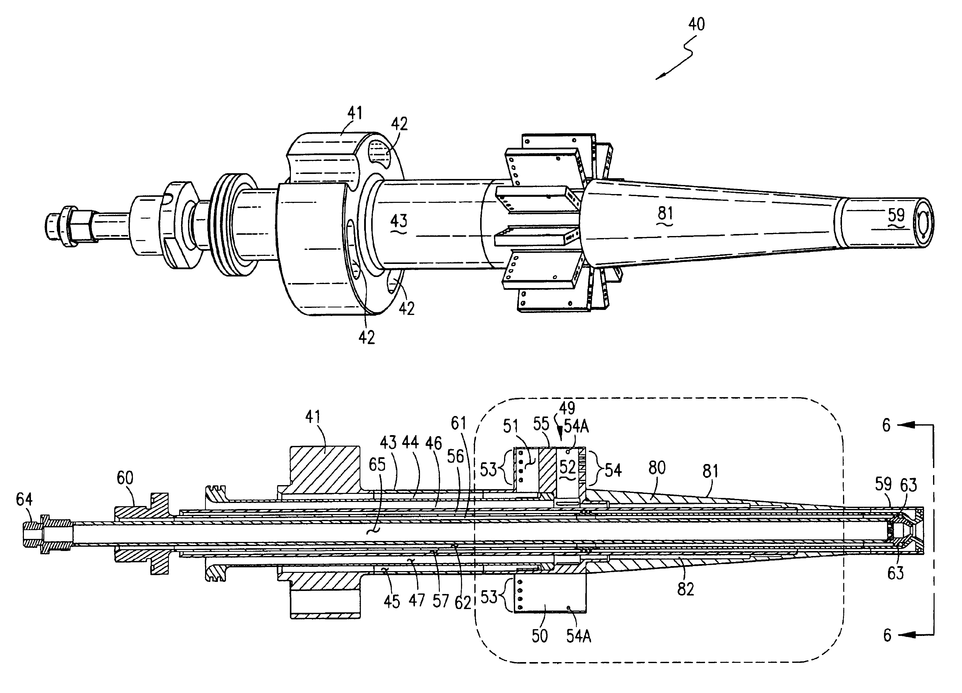
[0028]A dual fuel premix nozzle 40 is shown in detail in FIGS. 3 through 6. Dual fuel premix nozzle 40 has a base 41 with three through holes 42 for bolting premix fuel nozzle 40 to a housing 75 (see FIG. 7). Extending from base 41 is a first tube 43 having a first outer diameter, a first inner diameter, a first thickness, and opposing first tube ends. Within premix fuel nozzle 40 is a second tube 44 having a second outer diameter, a second inner diameter, a second thickness, and opposing second tube ends. The second outer diameter of second tube 44 is smaller than the first inner diameter of first tube 43 thereby forming a first annular passage 45 between the first and second tubes, 43 and 44, respectively. Dual fuel premix nozzle 40 further contains a third tube 46 having a third outer diameter, a third inner diameter, a third thickness, and opposing third tube ends. The third outer diameter of third tube 46 is smaller than said second inner diameter of second tube 44, thereby for...


PUM


Abstract

A dual fuel premix nozzle and method of operation for use in a gas turbine combustor is disclosed. The dual fuel premix nozzle utilizes a fin assembly comprising a plurality of radially extending fins for injection of gas fuel and compressed air in order to provide a more uniform injection pattern and homogeneous mixture. The premix fuel nozzle includes a plurality of coaxial passages, which provide gaseous fuel and compressed air to the fin assembly. When in liquid fuel operation, the gas circuits are purged with compressed air and liquid fuel and water pass through coaxial passages to the tip of the dual fuel premix fuel nozzle, where they inject liquid fuel and water into the secondary combustion chamber. An alternate embodiment includes an additional gas fuel injection region located along a conically tapered portion of the premixed fuel nozzle, downstream of the fin assembly. A second alternate embodiment is disclosed which reconfigures the injector assembly and fuel injection locations to minimize flow blockage issues at the injector assembly and simplify fuel nozzle manufacturing.

Description

[0001]This is a continuation-in-part of application Ser. No. 10 / 195,823 filed Jul. 15, 2002, now U.S. Pat. No. 6,722,132.BACKGROUND OF THE INVENTION[0002]1. Field of the Invention[0003]This invention relates generally to a fuel and air injection apparatus and method of operation for use in a gas turbine combustor for power generation and more specifically to a device that reduces the emissions of nitrogen oxide (NOx) and other pollutants by injecting gaseous fuel into a combustor in a premix condition while including liquid fuel capability.[0004]2. Description of Related Art[0005]In an effort to reduce the amount of pollution emissions from gas-powered turbines, governmental agencies have enacted numerous regulations requiring reductions in the amount of emissions, especially nitrogen oxide (NOx) and carbon monoxide (CO). Lower combustion emissions can be attributed to a more efficient combustion process, with specific regard to fuel injectors and nozzles. Early combustion systems u...

Claims


Application Information

Patent Timeline
Patent Type & Authority Patents(United States)
IPC IPC(8): F23R3/36F23R3/28F23L7/00
CPCF23L7/002F23R3/286F23R3/36F23D2209/30F23D2214/00F23D2900/00008F23D2900/14004
Inventor STUTTAFORD, PETERJENNINGS, STEPHEN T.MCMAHON, RYANRIZKALLA, HANYCIRES, ALFREDO
Owner ANSALDO ENERGIA SWITZERLAND AG
Learn More