
Distributed feed fuel cell stack

a fuel cell and stack technology, applied in the direction of fuel cells, fuel cells, electrochemical generators, etc., can solve the problems of poor thermal and fuel management, short life-span or even stack damage, and large temperature variations in the stack, so as to improve thermal management, improve thermal distribution, mass and thermal integration, and improve thermal management.

Inactive Publication Date: 2005-06-09
ILLINOIS INSTITUTE OF TECHNOLOGY
View PDF4 Cites 10 Cited by
  • Summary
  • Abstract
  • Description
  • Claims
  • Application Information

AI Technical Summary

Benefits of technology

[0007] The present invention allows the fuel or oxidant or both to be fed incrementally and distributed around the stack to achieve spatial uniformity of the reaction leading to improved thermal management without imparting stack or system performance. The result is a fuel cell with improved thermal distribution, mass and thermal integration, higher power densities, higher stack and system efficiencies, lower thermal stresses, and faster response while improving life span and rate of performance deterioration for the cell. A great practical effect for IR fuel cells of the present invention can be achieved through a large reduction of steam used in the IR fuel cells thus making a big difference in capital and operational costs. The present invention may further reduce the need for preforming fuel / oxidant mixtures.
[0009] The distributed feed fuel cell of the present invention can provide a plurality of discrete locations within the fuel cell including an initial feed location at the front of the fuel cell channel. The distributed feed fuel cell of the present invention can provide a fuel cell of internal steam reforming type or the external steam reforming cell. The distributed feed fuel cell of the present invention can provide the fuel cell with a substantially uniform heat generation profile during operation due to substantially uniform reaction rates along the length of the fuel cell channel. The distributed feed fuel cell of the present invention can provide a uniform temperature profile is between about 800 and about 1100 degrees C. to ensure efficient operation of the cell. The distributed feed fuel cell of the present invention can provide a substantially uniform current density during operation.
[0010] The distributed feed fuel cell of the present invention can provide the fuel cell having a distributed feed flow rate profile such that the hydrogen to steam ratio (HSR) is substantially spatially uniform during operation and a preferred steam to carbon ratio (SCR) of less than 1:1 for the fuel cell during operation such as a ratio of about 1:2 for the fuel cell during operation.

Problems solved by technology

Both the SOFC and the MCFC stacks have some differences in term of their operating conditions, components and electrochemistry, however, they share common problems, including poor thermal and fuel management.
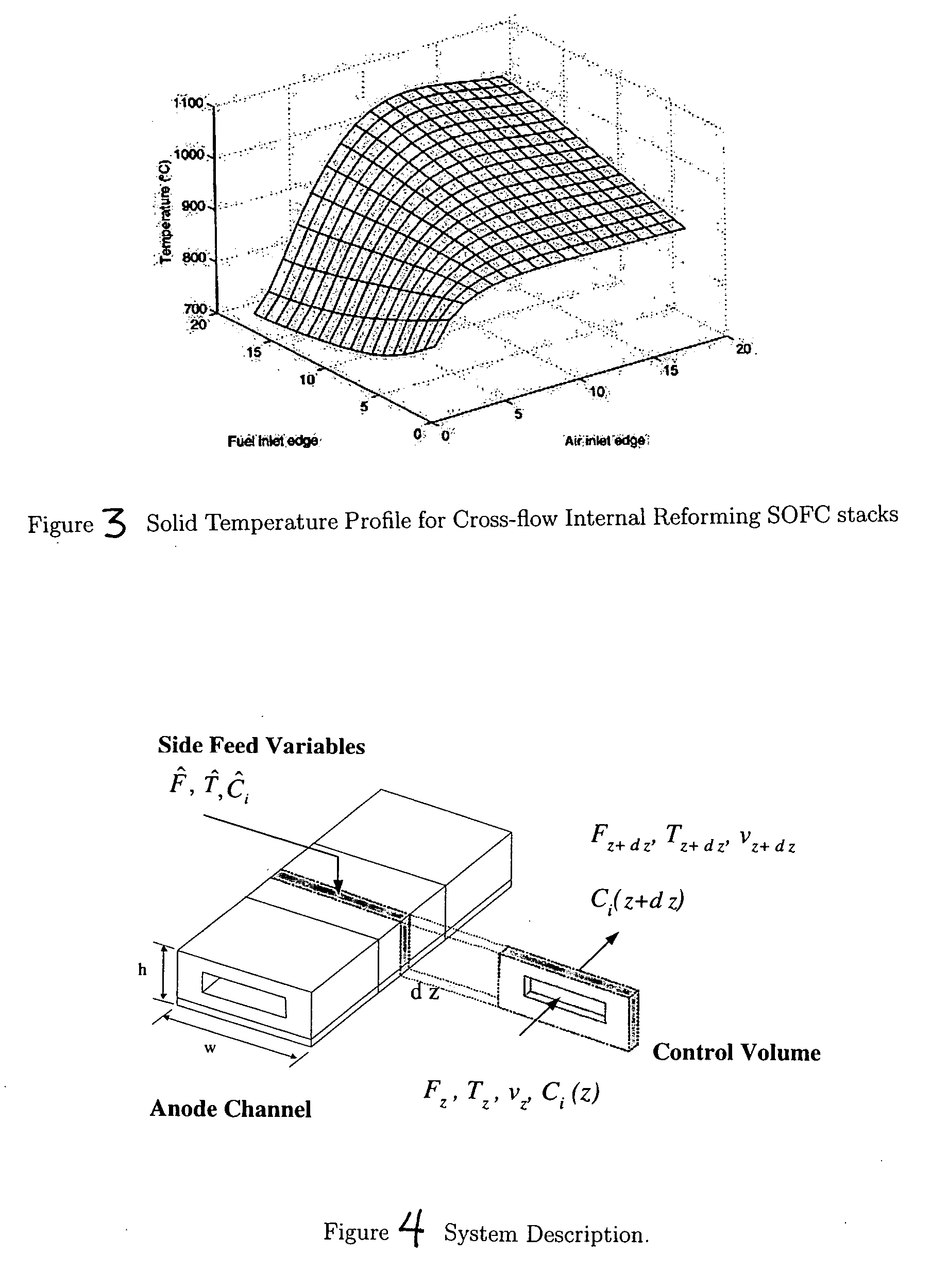
Both internal and external reforming suffer from large temperature variations within the stack.
These temperature variations cause severe thermal stresses and material corrosion, which lead to a shorter life-span or even stack damage.
Furthermore, the reforming reaction produces hydrogen and consumes steam, which is the product of the electrochemical reaction.
Unfortunately, a mismatch in reaction kinetics prevents the full attainment of this synergy.

Method used


Image

  • Distributed feed fuel cell stack
  • Distributed feed fuel cell stack
  • Distributed feed fuel cell stack

Examples


Embodiment Construction

Kinetics and Operation

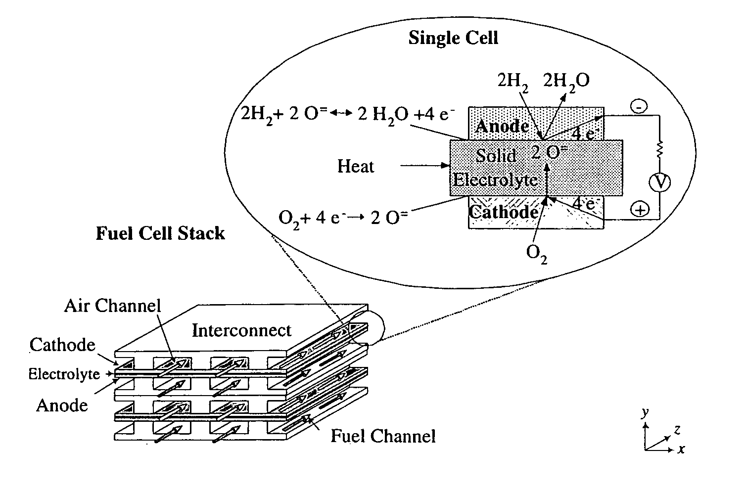
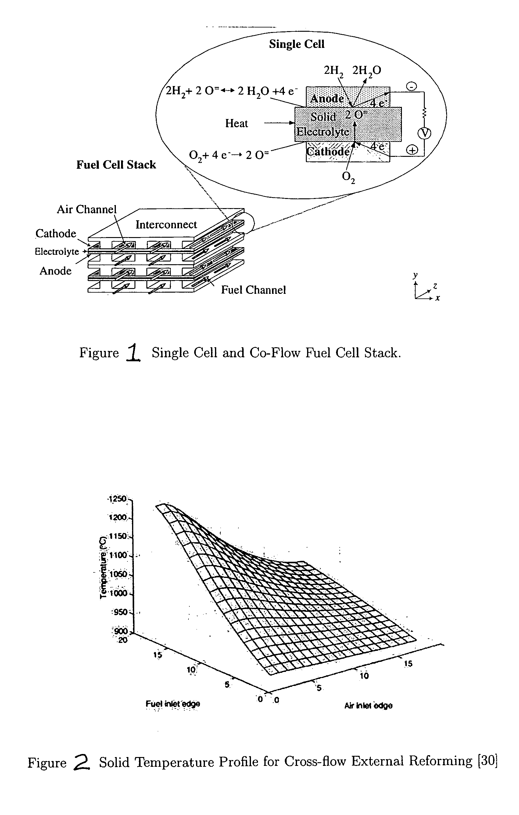
[0035] A fuel cell stack consist of four building blocks, which are anode, cathode, electrolyte and interconnect, as shown in FIG. 1. The oxidant, usually air, is fed on the cathode side to provide the needed oxygen for the electrochemical reaction, in addition, it serves as a coolant, when the fuel cell is hydrogen fed. However, air provides the heat needed, when the fuel cell stack is methane fed (i.e. internal reforming stack). The fuel is fed on the anode side. Oxygen ions are conducted by the electrolyte and electrons are conducted by the interconnect 2.1. Equations 2.1 and 2.2 are the anode hydrogen and the cathode electrochemical reactions respectively. H2+O=⟶H2⁢O+2⁢ ⁢e-(2.1)12⁢O2+2⁢ ⁢e-⟶O=(2.2)

The sum of Equations 2.1 and 2.2 will lead to the cell overall reaction, which is shown below.

The sum of Equations 2.1 and 2.2 will lead to the cell overall reaction, which is shown below. H2+12⁢ ⁢O2⟶H2⁢O(2.3)

[0036] As the reaction described by Equation 2.3...


PUM


Abstract

A fuel cell having a distributed fuel feed in which the heat generation profile can be better controlled. Fuel channel stack and system efficiency improvements are achieved.

Description

[0001] This application claims priority from U.S. Provisional Application No. 60 / 517,463 filed 5 Nov. 2003.BACKGROUND OF THE INVENTION DISCUSSION OF THE RELATED ART [0002] More than ever before, there is a strong need for a more efficient energy conversion device and a low emission power generation system. This demand is a result of strict emission rules and regulations, and the need to slow down the growing demand for fossil fuel. Fuel cells make an excellent candidate because of their high efficiency and very low emissions, which can be described as electrochemical devices that convert chemical energy into electrical energy. [0003] High temperature fuel cells, which are solid oxide fuel cell (SOFC) and molten carbonate fuel cell (MCFC), operate from 650° C. to 1000° C. and can attain an overall net low system efficiency of more than 70%. The high operating temperatures allow for the exhaust temperature to be utilized in bottoming cycles and / or co-generation. In addition, the heat ...

Claims


Application Information

Patent Timeline
IPC IPC(8): H01M8/04H01M8/12H01M8/14H01M8/24
CPCH01M8/0258H01M8/04089H01M8/0618H01M8/0637Y02E60/526H01M2008/147Y02E60/50Y02E60/525H01M2008/1293H01M8/244H01M8/2432H01M8/2457H01M8/2483
Inventor AL-QATTAN, AYMAN M.CHMIELEWSKI, DONALD L.AL-HALLAJ, SAID
Owner ILLINOIS INSTITUTE OF TECHNOLOGY
Learn More