Heating device and fuser utilizing electromagnetic induction

a heating device and fuser technology, applied in the field of fusers, can solve the problems of deteriorating printing quality, uneven heat generation of heating members, etc., and achieve the effects of improving workability, reducing production costs, and reducing production costs

Inactive Publication Date: 2005-05-03
PANASONIC CORP
View PDF24 Cites 10 Cited by
  • Summary
  • Abstract
  • Description
  • Claims
  • Application Information

AI Technical Summary

Benefits of technology

[0017]According to fifth aspect of the invention, the coil guide member comprises an opening and a housing that is curved so as to cover the heating member and accommodates the heating member. With this configuration, the exciting coil and the heating member can be manufactured independently and can be separated from each other. Therefore, an advantageous effect is obtained that the inspection, maintenance, repairing, etc. can be improved in workability.
[0018]According to the sixth aspect o

Problems solved by technology

The AC magnetic field generated by the energized exciting coil is not uniform over the entire range and hence the heat gene

Method used


Image

  • Heating device and fuser utilizing electromagnetic induction
  • Heating device and fuser utilizing electromagnetic induction
  • Heating device and fuser utilizing electromagnetic induction

Examples


Embodiment Construction

[0028]Embodiments of the present invention will be hereinafter described with reference to FIGS. 1 to 8. In these drawings, the same members are given the same reference symbol. And redundant descriptions will be omitted.

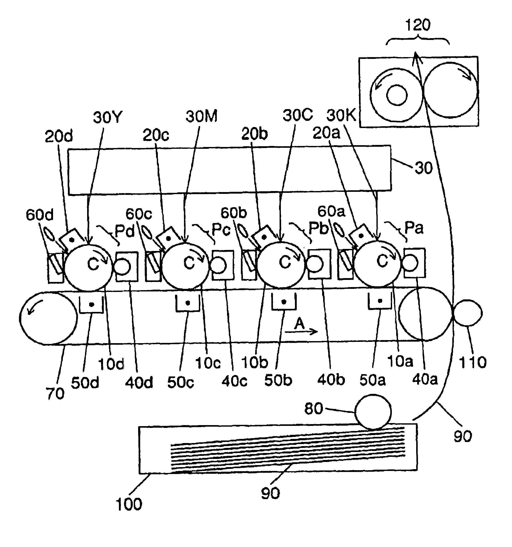
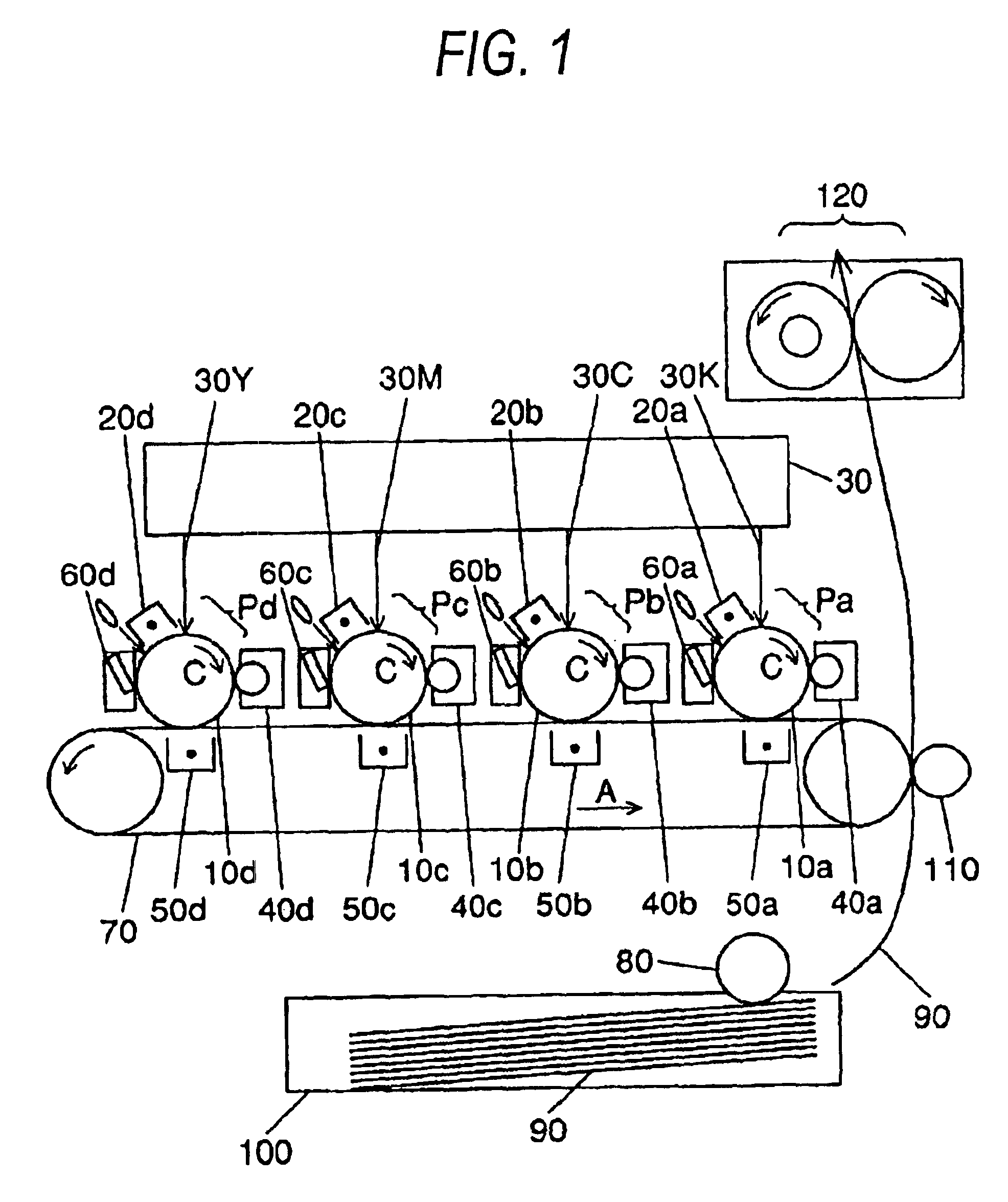
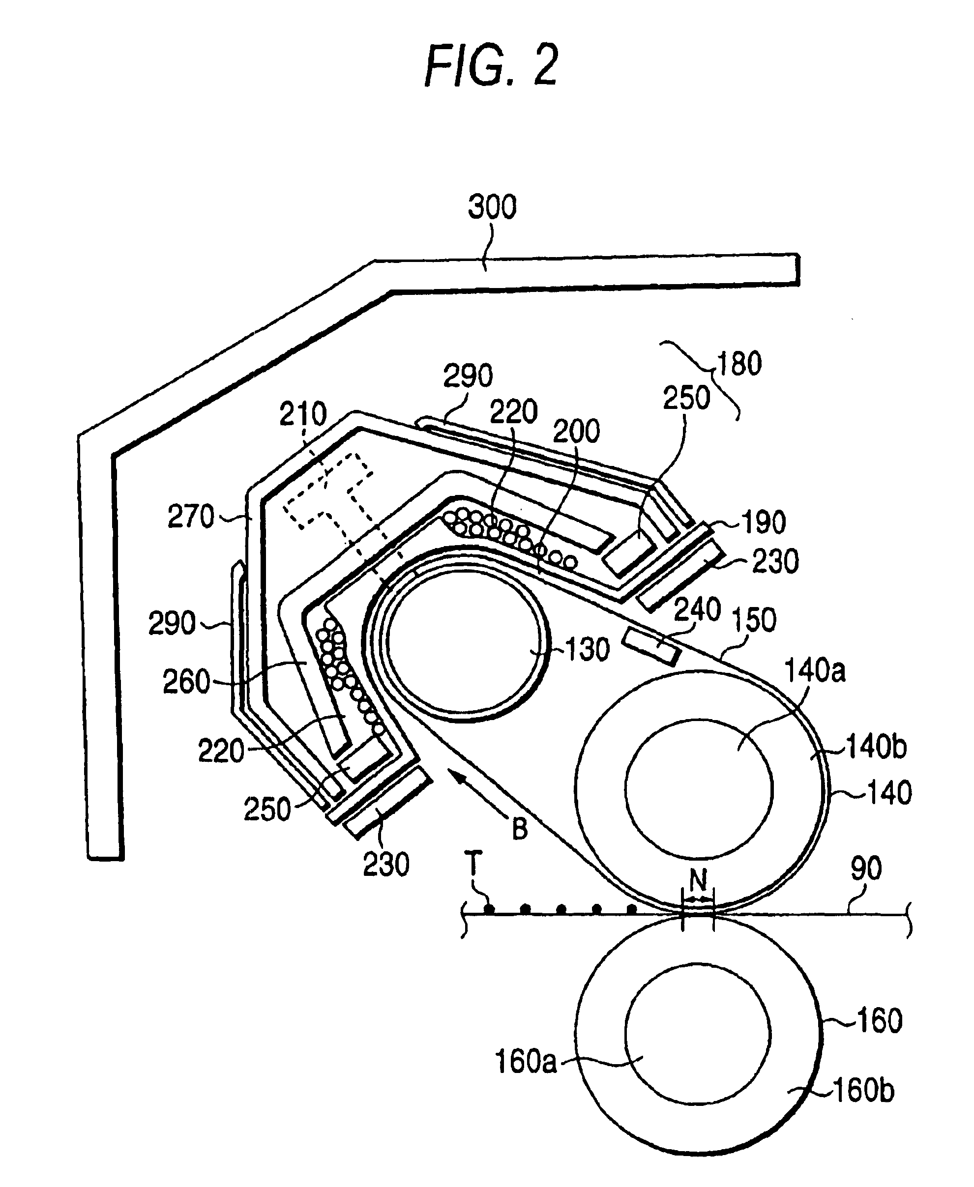
[0029]FIG. 1 illustrates the configuration of an image forming apparatus that is equipped with a fuser according to an embodiment of the invention. FIG. 2 illustrates the configuration of the fuser according to the embodiment of the invention that is used in the image forming apparatus of FIG. 1. FIG. 3 is a cutaway view illustrating the structure of a heating roller that is a component of the fuser of FIG. 2. FIG. 4 illustrates how an exciting coil of an induction heating unit according to the embodiment of the invention is wound. FIG. 5 illustrates how the exciting coil of the induction heating unit according to the embodiment of the invention is wound. FIG. 6 illustrates how the exciting coil of the induction heating unit according to the embodiment of the invent...


PUM


Abstract

A heating device utilizing electromagnetic induction is provided with an induction heating unit that is opposed to a heating member and causes the heating member to heat through electromagnetic induction. The induction heating unit has an exciting coil for generating a magnetic field and a coil guide member on which the exciting coil is wound. The exciting coil is formed in at least two layers in such a manner that a first layer is formed on a circumferential surface of the coil guide member by winding a plurality of turns and a second layer is formed around and outside the first layer on the side opposite to the coil guide member, and winding of each of the second layer and following layers is started from a position close to a winding start position of the first layer.

Description

BACKGROUND OF THE INVENTION[0001]The present invention relates to a fuser that is used in an electrostatic recording type image forming apparatus such as a copying machine, a facsimile, and a printer. More specifically, the invention relates to a heating device and a fuser utilizing electromagnetic induction.[0002]In recent years, in image forming apparatus such as printers, copiers, and facsimiles, market requirements about the energy consumption and the processing speed have become higher. To attain performance that meets those requirements, it is important to increase the thermal efficiency of fusers that are used in image forming apparatus.[0003]In image forming apparatus, an unfused toner image is formed on a recording medium such as a recording sheet, printing paper, photosensitive paper, or electrostatic recording paper by an image transfer type or direct type image forming process such as xerography, electrostatic recording, or magnetic recording. Fusers of contact heating t...

Claims


Application Information

Patent Timeline
IPC IPC(8): G03G15/20H05B6/14
CPCH05B6/145G03G15/2053
Inventor MONDA, YUICHITORIKAI, EIJISOEDA, KAZUHIKOKAJIWARA, TADAYUKISHIMIZU, TADAFUMIKITAGAWA, SHOUICHISAMEI, MASAHIROMATSUO, KAZUNORIMATSUZAKI, KEIICHIASAKURA, KENJITATEMATSU, HIDEKI
Owner PANASONIC CORP
Why Eureka
Try Eureka