
Refrigeration system and its condensing apparatus

a refrigeration system and condensing technology, applied in the field of refrigeration systems and their condensing apparatus, can solve the problems of poor refrigeration performance and inability to meet the needs of refrigeration, and achieve the effect of improving the separation performance of vapor and liquid

Inactive Publication Date: 2005-07-12
MAHLE INT GMBH
View PDF15 Cites 3 Cited by
  • Summary
  • Abstract
  • Description
  • Claims
  • Application Information

AI Technical Summary

Benefits of technology

[0027]In the heat exchanger with a receiver-tank of the first invention, since the embedding portion of the receiver-tank joint member is secured to one of the headers in the state where the embedding portion is embedded in one of the headers, the installation space of the embedding portion can be omitted. Furthermore, since the flange-like partition piece is integrally provided at the inlet or its vicinity of the inlet flow passage at the upper end surface of the embedding portion to thereby divide the inside of one of the headers, it is not necessary to attach an additional partition for dividing the inside of the header, and therefore the number of components can be decreased.
[0031]In this structure, the assembling position of the receiver-tank can be positioned lower. Thus, a longer receiver-tank can be used, which enables to keep the tank volume large enough.
[0035]In this structure, since the upper end opening area of the descent passage can be formed larger as compared with the case where a passage is disposed in parallel to the axis of the header, the refrigerant can be introduced smoothly and efficiently, and therefore the pressure loss of the refrigerant can be reduced.
[0037]In this structure, since the refrigerant can be introduced into the receiver-tank in a stabilized manner, and therefore the vapor-liquid-separation performance by the receiver-tank can be improved.
[0039]In this structure, the refrigerant can be introduced into the receiver-tank in a further stabilized manner, and therefore the vapor-liquid-separation performance can be further improved.<Second Invention>

Problems solved by technology

This tends to cause an excessive or shortage of sealed amount of refrigerant, resulting in unstable refrigeration performance.
This makes it difficult to stably supply a liquefied refrigerant, resulting in poor refrigeration performance.

Method used


Image

  • Refrigeration system and its condensing apparatus
  • Refrigeration system and its condensing apparatus
  • Refrigeration system and its condensing apparatus

Examples


Embodiment Construction

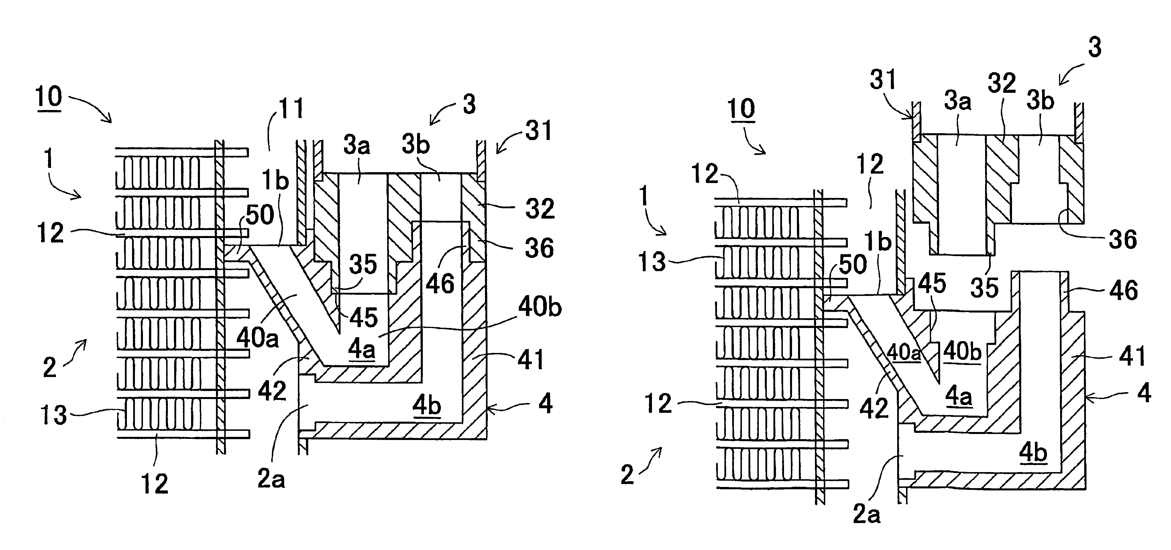
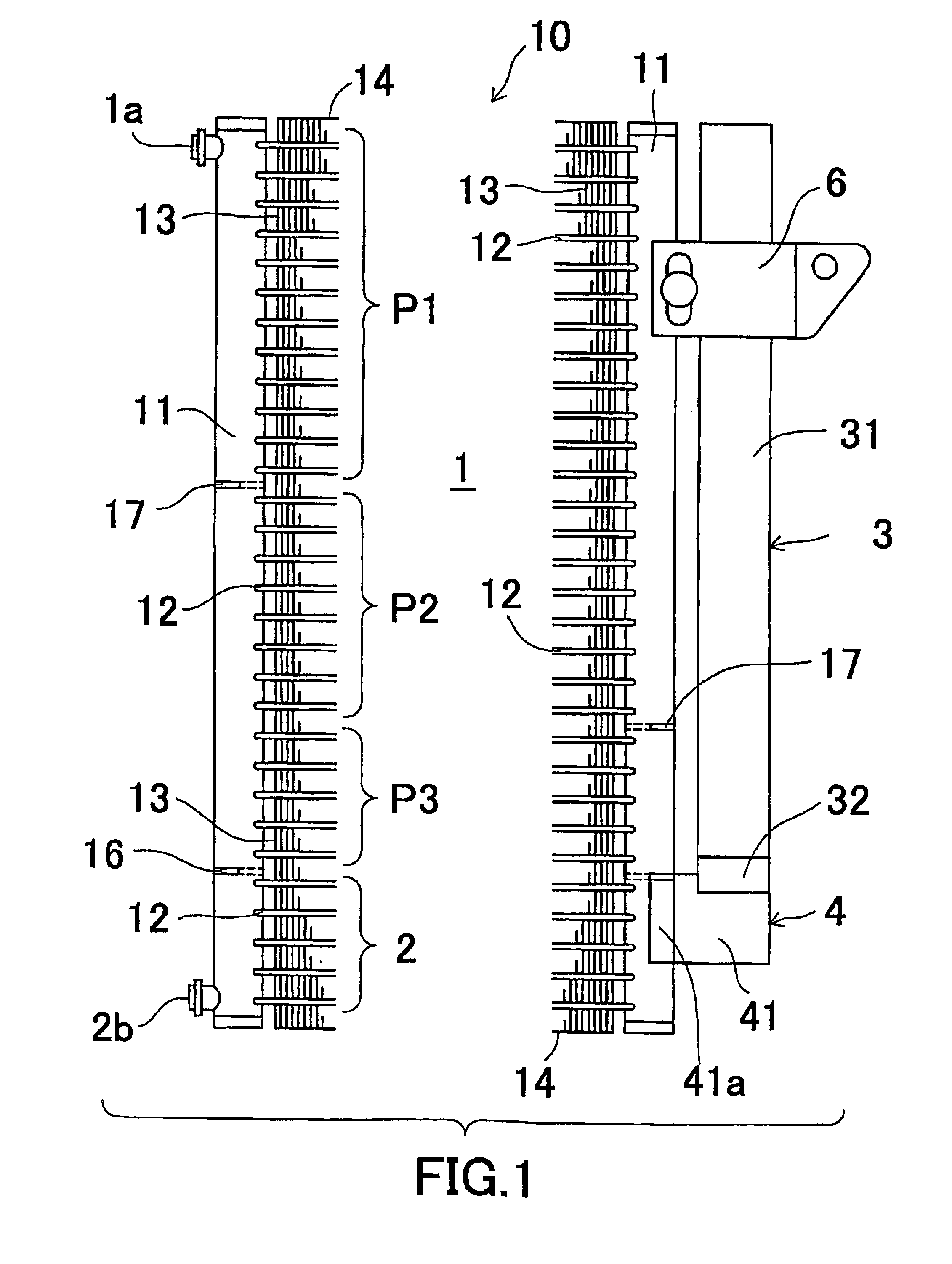
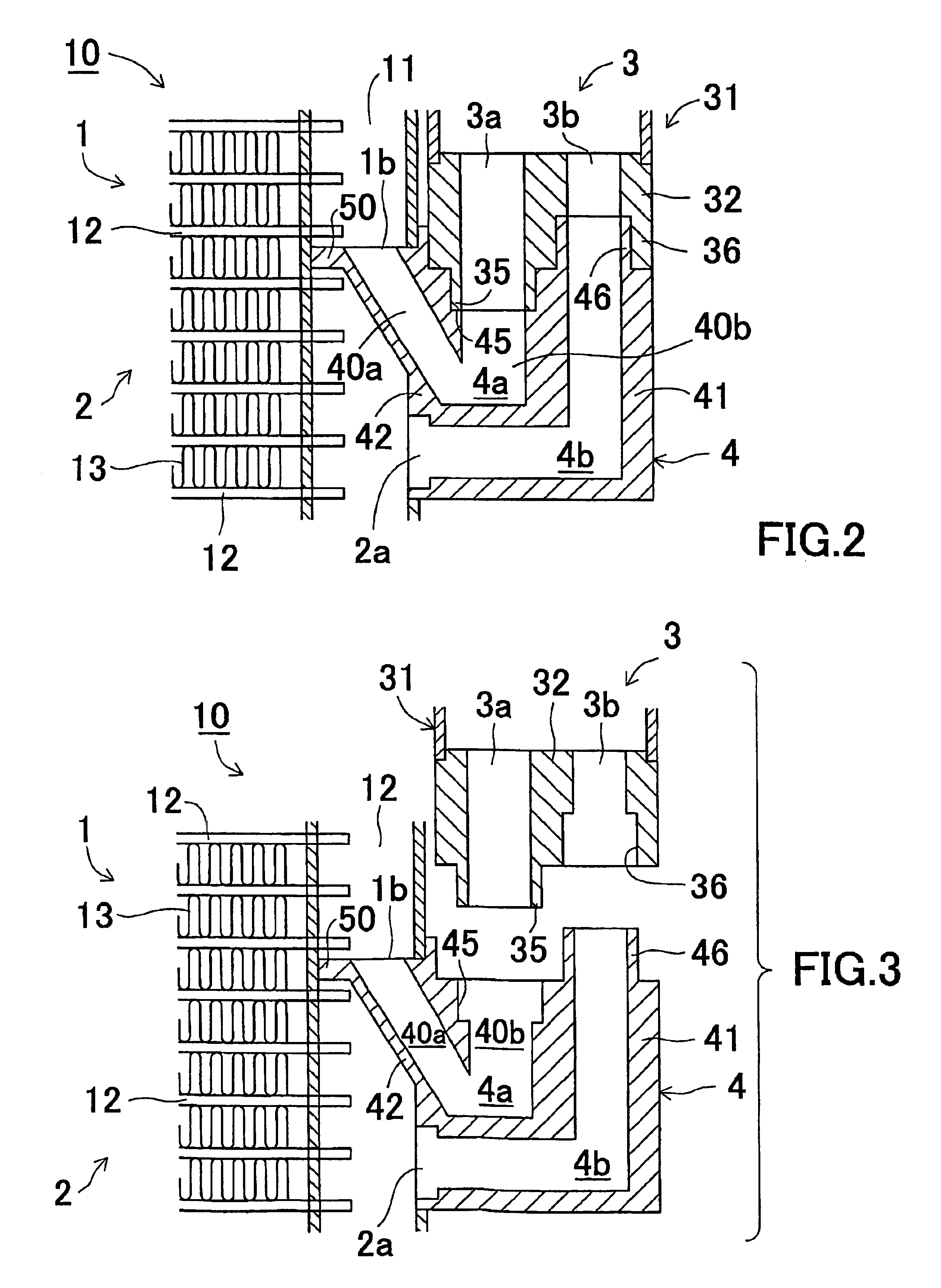
[0143]FIG. 1 is a front view showing the both side portions of the heat exchanger with a receiver-tank according to an embodiment of the present invention, FIG. 2 is an enlarged front cross-sectional view showing the block flange and its vicinity of the heat exchanger of the embodiment, and FIG. 3 is an exploded front cross-sectional view showing the block flange and its vicinity of the heat exchanger of the embodiment.

[0144]As shown in these figures, this heat exchanger is provided with a multi-flow type heat exchanger main body 10, a receiver-tank 3 and a block flange 4 constituting a joint member for connecting the receiver-tank 3 to the heat exchanger main body 10.

[0145]The heat exchanger main body 10 includes a pair of right and left vertical headers 11 disposed at a certain distance. Between this pair of headers 11, a number of horizontally disposed flat tubes 12 as heat exchanging tubes are arranged in parallel with each other at certain intervals with opposite ends thereof c...


PUM


Abstract

A heat exchanger with a receiver-tank includes a heat exchanger main body, a receiver-tank and a block flange. The flange includes a main body, an embedding portion to be attached to one of headers in an embedded state, an inlet flow passage with an inlet side end portion disposed at an upper end of the embedding portion, the inlet flow passage communicating with a condensing portion of the heat exchanger main body, and an outlet flow passage with an outlet side end portion disposed at a side surface of the embedding portion, and the outlet flow passage communicating with a subcooling portion. A flange-like partition piece is formed at an upper end periphery of the embedding portion of the flange, and the peripheral edge of the partition piece is joined to the inner peripheral surface of one of the headers.

Description

[0001]Priority is claimed to Japanese Patent Application No. 2002-43367 filed on Feb. 20, 2002 and a U.S. Provisional Patent Application No. 60 / 363,285 filed on Mar. 12, 2002, the disclosure of which are incorporated by reference in their entireties.CROSS REFERENCE TO RELATED APPLICATIONS[0002]This application is an application filed under 35 U.S.C. § 111(a) claiming the benefit pursuant to 35 U.S.C. § 119(e)(1) of the filing date of U.S. Provisional Application No. 60 / 363,285 filed on Mar. 12, 2002 pursuant to 35 U.S.C. § 111(b).TECHNICAL FIELD[0003]The present invention relates to a condensing apparatus including a heat exchanger with a receiver-tank, a receiver-tank joint member, receiver-tank assembling structure of a heat exchanger suitably used for, for example, a car air-conditioning refrigeration apparatus, and also relates to a refrigeration system.BACKGROUND ART[0004]In recent years, in a condensing process of a refrigerant in a refrigeration cycle for a car air-conditioni...

Claims


Application Information

Patent Timeline
IPC IPC(8): F25B39/04F28F9/04F25B15/04F25B40/02F28D1/053
CPCF25B39/04F28D1/05375F28F9/0246F28F9/0253F28F9/0256F25B40/02F25B2339/044F25B2339/0446F28D2021/0084F25B43/00B60H1/32
Inventor SENO, YOSHIHIKOKAMOSHIDA, OSAMUYAMAZAKI, KEIJI
Owner MAHLE INT GMBH
Learn More