Apparatus and method for radar-based level gauging

a level gauging and radar technology, applied in the direction of antennas, engine lubrication, liquid/fluent solid measurement, etc., can solve the problems of large discrepancy in many applications, inability to meet custody transfer accuracy, etc., to achieve the effect of low cost, low cost and reduced errors

Inactive Publication Date: 2005-07-12
ROSEMOUNT TANK RADAR
View PDF12 Cites 42 Cited by
  • Summary
  • Abstract
  • Description
  • Claims
  • Application Information

AI Technical Summary

Benefits of technology

[0022]A main advantage of the present invention is that level gauging through a tube with high accuracy may be performed without any prior knowledge of the composition and pressure of the gas present above the surface, which is gauged.
[0023]Another advantage of the present invention is that errors introduced by conditions of the tube may be reduced by means of dual mode measurements.
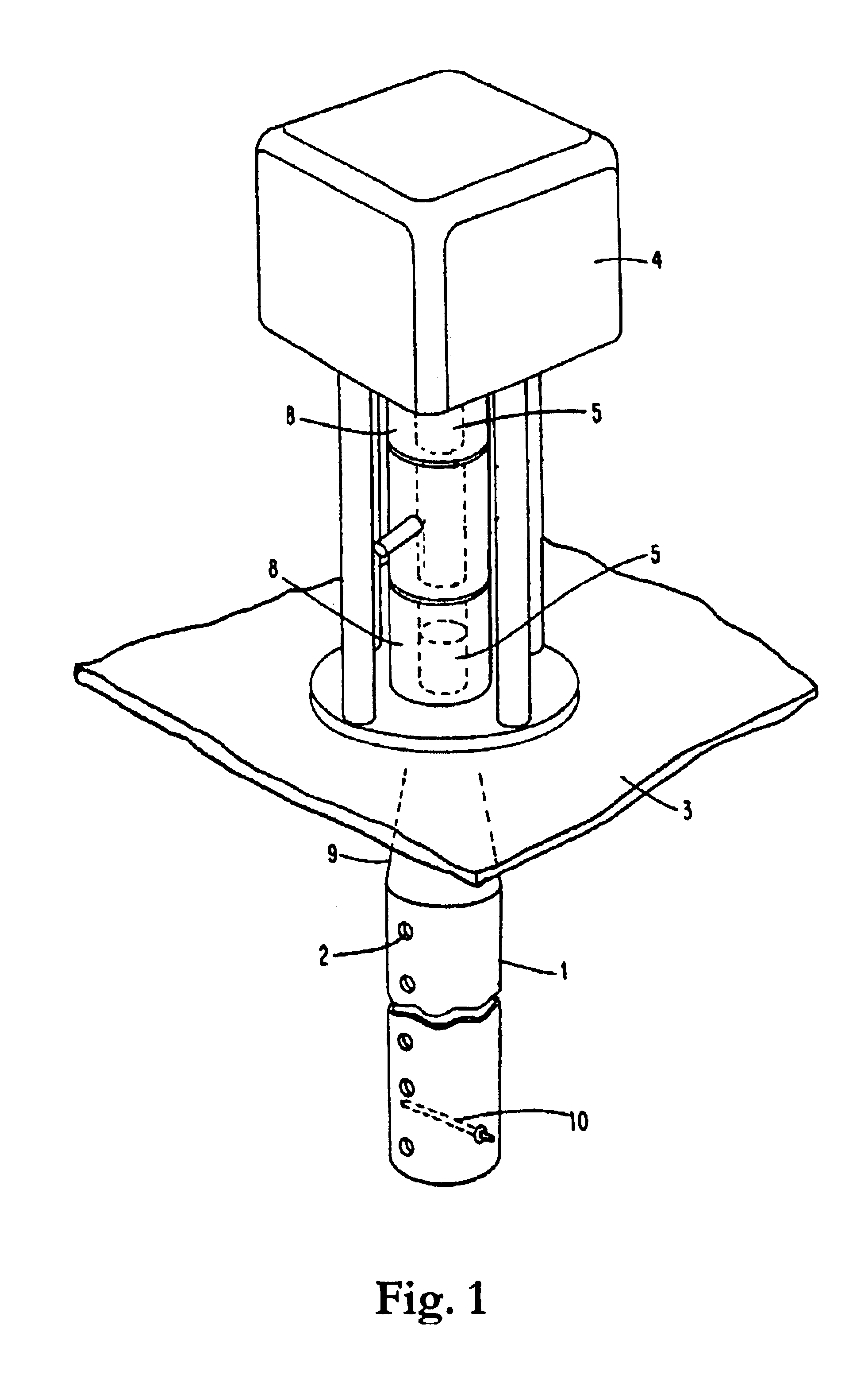
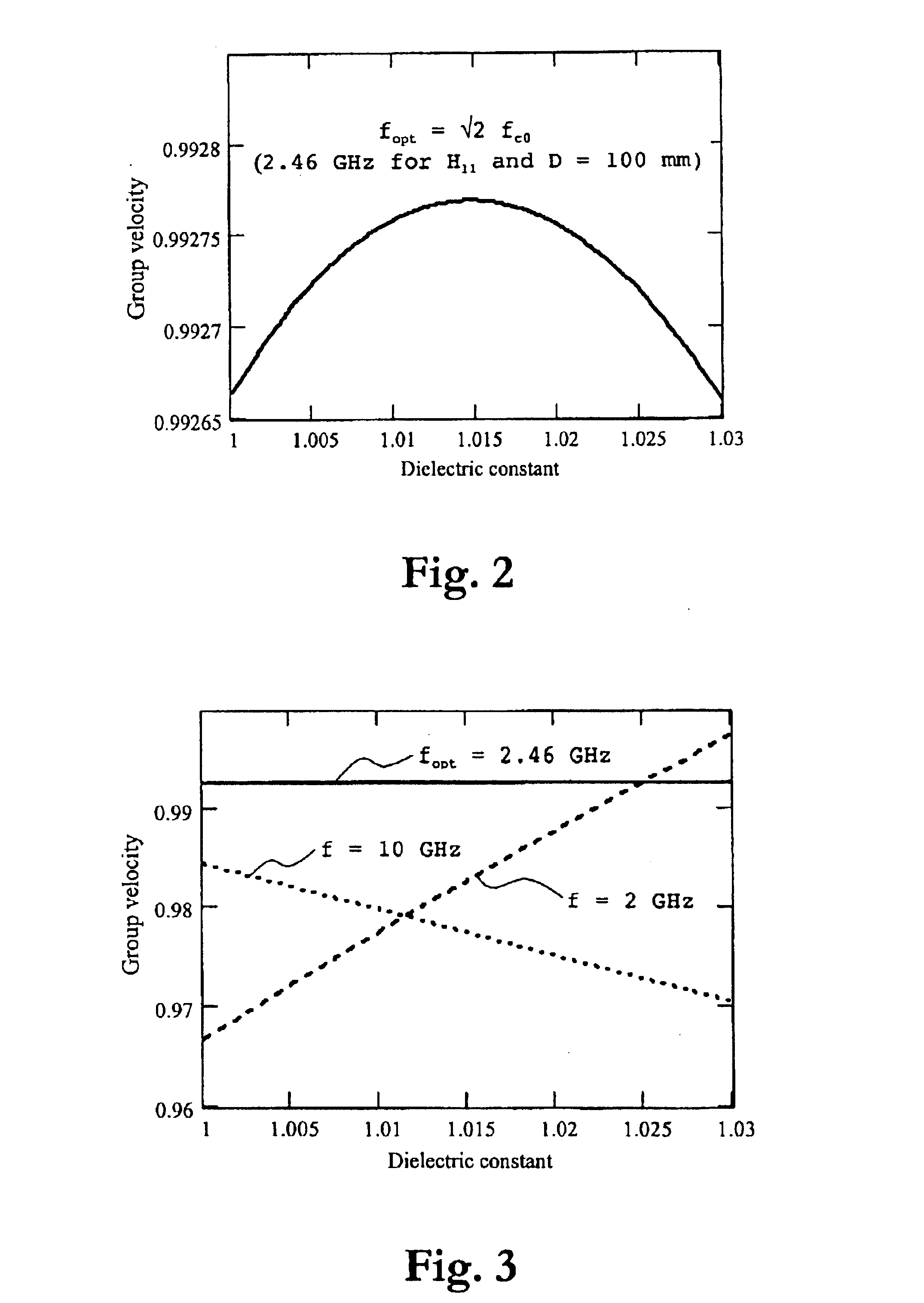
[0024]Still another advantage of the invention is that by selecting a frequency close to the optimum frequency as defined above for the dielectric constant range of 1-1.03 influences from e.g. a variable amount of hydrocarbon droplets within the tube and thin hydrocarbon layers of variable thickness on the inner walls of the tube are minimized.
[0025]Further characteristics of the invention, and advantages thereof, will be evident from the detailed description of preferred embodiments of the present invention given hereinafter and the accompanying FIGS. 1-12, which are given by way of illustration only, and thus are not limitative of the present invention.
[0026]In this description, the waveguide designations H11, E01, H01 etc. will be used as being a parallel and fully equivalent system to the designations TE11, TM01, TE01 etc.

Problems solved by technology

Such large discrepancy is in many applications, such as in custody transfer applications, not acceptable.
However, the requirements for custody transfer vary quite much from country to country and from organization to organizations, but obviously the example as identified above does not comply with any custody transfer accuracy.

Method used


Image

  • Apparatus and method for radar-based level gauging
  • Apparatus and method for radar-based level gauging
  • Apparatus and method for radar-based level gauging

Examples


Embodiment Construction

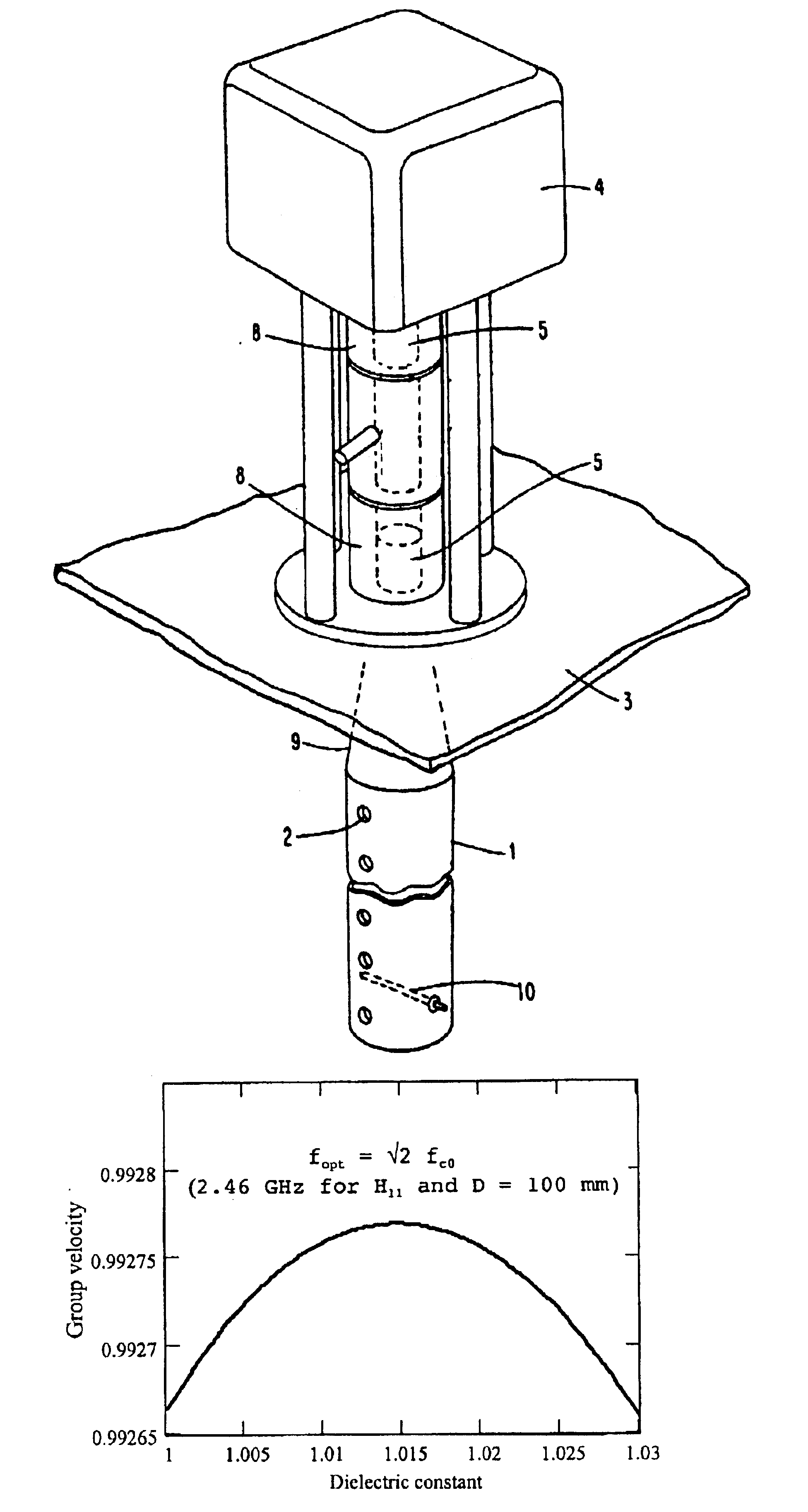
[0037]With reference to FIG. 1, which schematically illustrates, in a perspective view, an apparatus aimed for radar-based level gauging, a preferred embodiment of the present invention will be described. The apparatus may be a frequency modulated continuous wave (FMCW) radar apparatus or a pulsed radar apparatus or any other type of distance measuring radar, but is preferably the former. The radar apparatus may have a capability of transmitting a microwave signal at a variable frequency, which is adjustable.

[0038]In the Figure, 1 designates a substantially vertical tube or tube that is rigidly mounted in a container, the upper limitation or roof of which is designated by 3. The container contains a liquid, which may be a petroleum product, such as crude oil or a product manufactured from it, or a condensed gas, which is stored in the container at overpressure and / or cooled. Propane and butane are two typical gases stored as liquids.

[0039]The tube 1 is preferably of a metallic mater...


PUM


Abstract

An apparatus for gauging the level of a liquid, above which a gas having a dielectric constant within a predetermined dielectric constant range exists, comprises a transmitter for transmitting a microwave signal in a propagation mode in a tube through the gas towards the liquid surface; a receiver for receiving the microwave signal reflected against the liquid surface and propagating back through the tube; and a processing device for calculating from the propagation time of the transmitted and reflected microwave signal the level of the liquid. In order to essentially avoid the influence on the calculated level by the dielectric constant of the gas above the liquid, the transmitter is adapted to transmit the microwave signal in a frequency band, at which the group velocity of the microwave signal in the propagation mode in the tube is, within the predetermined dielectric constant range, essentially independent of the dielectric constant.

Description

FIELD OF THE INVENTION[0001]The invention relates generally to radar-based level gauging, and more specifically the invention relates to apparatuses and methods for radar-based level gauging of the level of a liquid through a waveguide at high accuracy without prior knowledge of the exact gas composition and / or pressure above the surface of the liquid.BACKGROUND OF THE INVENTION AND RELATED ART[0002]A device for gauging the level of a liquid in a container comprises a transmitter for transmitting a microwave signal towards the surface of the liquid, a receiver for receiving the microwave signal reflected against the surface of the liquid, and a signal processing device for calculating the level of the liquid in the container from the propagation time of the transmitted and reflected microwave signal.[0003]Such device has become more and more important, particularly for petroleum products such as crude oil and products manufactured from it. By containers is here meant large container...

Claims


Application Information

Patent Timeline
Patent Type & Authority Patents(United States)
IPC IPC(8): H01Q1/22H01Q21/24H01Q13/00H01Q21/06H01Q13/02
CPCH01Q1/22H01Q1/225H01Q13/02H01Q21/062H01Q21/24
Inventor EDVARDSSON, KURT O.
Owner ROSEMOUNT TANK RADAR
Why Eureka
Try Eureka