

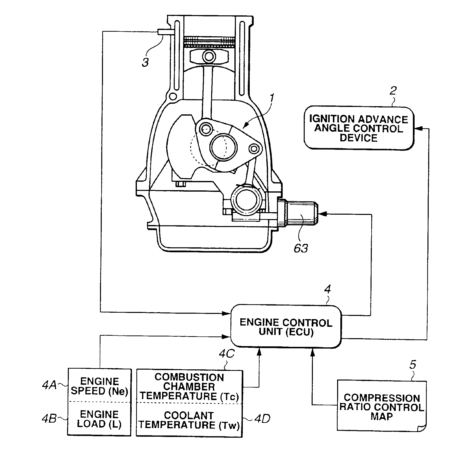
Compression ratio controlling apparatus and method for spark-ignited internal combustion engine
a technology of compression ratio and controlling apparatus, which is applied in the direction of electric control, ignition automatic control, machines/engines, etc., can solve the problems of torque hesitation, easy transient knocking,
- Summary
- Abstract
- Description
- Claims
- Application Information
AI Technical Summary
Benefits of technology
Problems solved by technology
Method used
Image

Examples
first embodiment
[0044]Whereas, in the first embodiment, during the transitional period of a state transition from the high load region to the low load region, compression ratio ε is not abruptly varied but reaches to target compression ratio after a predetermined period of time τ0 has passed from a time at which the engine load condition is changed from the high load region to the low load region.
[0045]FIGS. 7A through 7E show transient variations of the respective characteristic values according to the control of compression ratio ε executed in the first preferred embodiment of compression ratio controlling apparatus and indicates the same running situation as that shown in FIGS. 5A and 5E.
[0046]In this example of FIGS. 7A through 7E, a predetermined delay τs is provided and the compression ratio control is started from a time point at which predetermined period of delay time τs has passed to be directed toward the target compression ratio, in other words, toward the high compression ratio. Thus, ...
second embodiment
[0061]In the second embodiment, after the engine condition is transferred from the low load drive to the high load drive, a predetermined time delay (lag) denoted by τs2 (as shown in FIG. 15D) is provided so that the compression ratio control is started toward the target compression ratio, viz., the predetermined low compression ratio upon the passage of time corresponding to the delay of τs2. This compression ratio control causes compression ratio ε to be reached to target compression ratio εs during the high load after a predetermined period of time τ02 from a time at which the transitional variation in the engine load described above occurs. It is noted that broken lines shown in FIGS. 15B, 15C, and 15D denote their characteristics when compression ratio ε is quickly (speedily) reduced. The difference in ignition timing IT between the characteristics denoted by the dot line and solid line shown in FIG. 15C indicates a difference in a demanded advance angle. In addition, the level...
PUM
 Abstract
Description
Claims
Application Information