Power transfer apparatus

a technology of power transfer and transmission device, which is applied in the direction of gearing details, gearing, transportation and packaging, etc., can solve the problems of large transmission body, tight corner braking phenomenon, and difference in wheel speed between front and back, so as to achieve the effect of lightening and reducing the size of the transmission body

Active Publication Date: 2005-07-12
HONDA MOTOR CO LTD
View PDF9 Cites 9 Cited by
  • Summary
  • Abstract
  • Description
  • Claims
  • Application Information

AI Technical Summary

Benefits of technology

[0011]Consequently, an object of the present invention is to provide power tra

Problems solved by technology

In conventional four-wheel drive vehicles, in turning a corner of a small turning radius at low or middle speed in a four-wheel driving mode, there is caused a difference in wheel speed between front and rear wheels which is attributed to a difference in turning radius between the front and rear wheels, resulting in the occurrence of a tight corner braking phenomenon.
Incidentally, in the aforesaid transfer (the speed increasing apparatus) for four-wheel drive vehicles, at least two hydraulic or electromagnetic actuators are required as a po

Method used


Image

  • Power transfer apparatus
  • Power transfer apparatus
  • Power transfer apparatus

Examples


Embodiment Construction

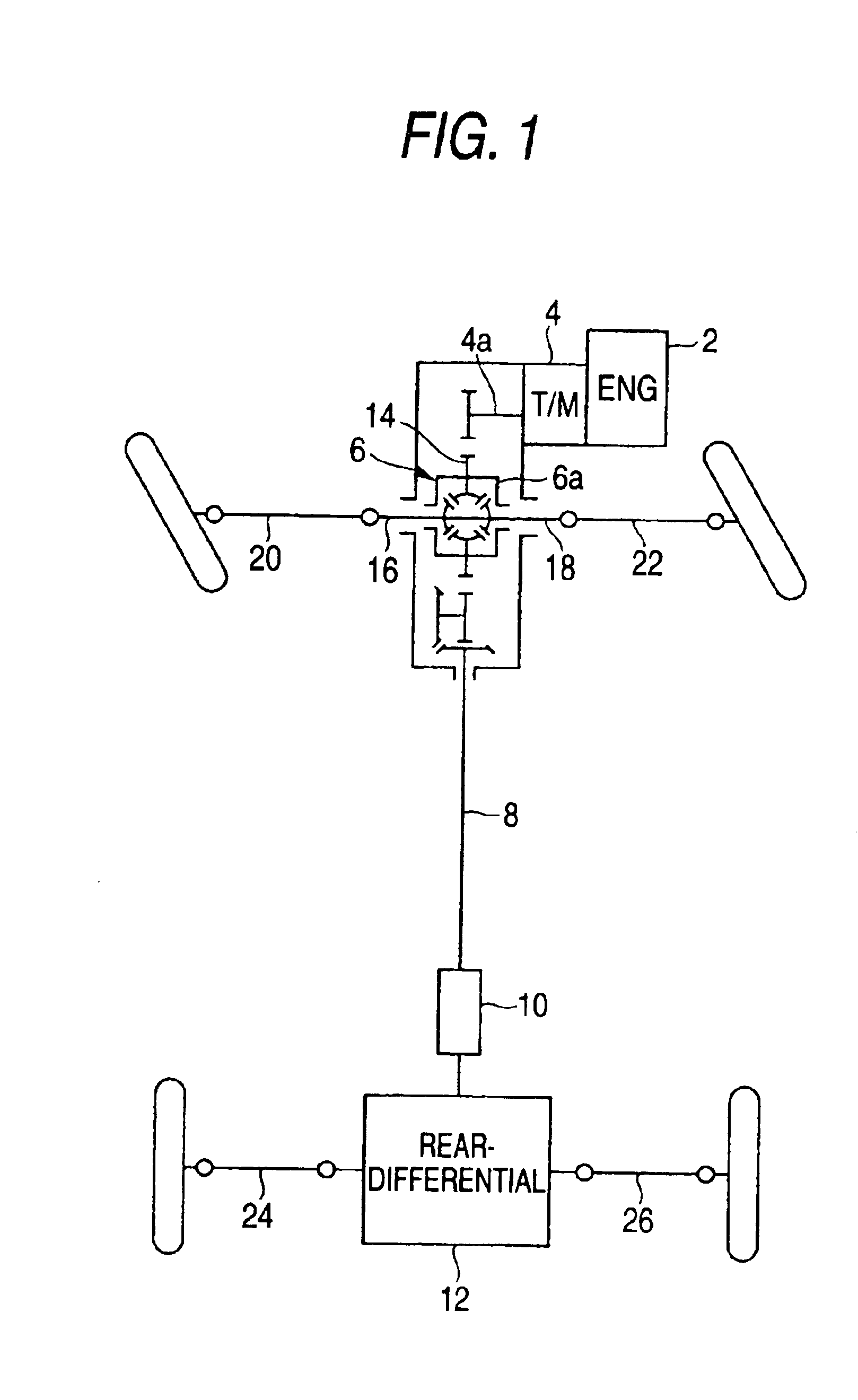
[0047]Referring to FIG. 1, there is shown a schematic view of a power train for a wheel-drive vehicle built based on a front-engine, front-drive (FF) vehicle to which a speed increasing apparatus (a power transfer apparatus) according to the present invention.

[0048]What should be noticed here is that the present invention is not limited to a four-wheel drive vehicle which is built based on the FF vehicle but may be applied to a four-wheel drive vehicle built based on a rear-engine, rear-drive (RR) vehicle or a front-engine, rear-drive (FR) vehicle.

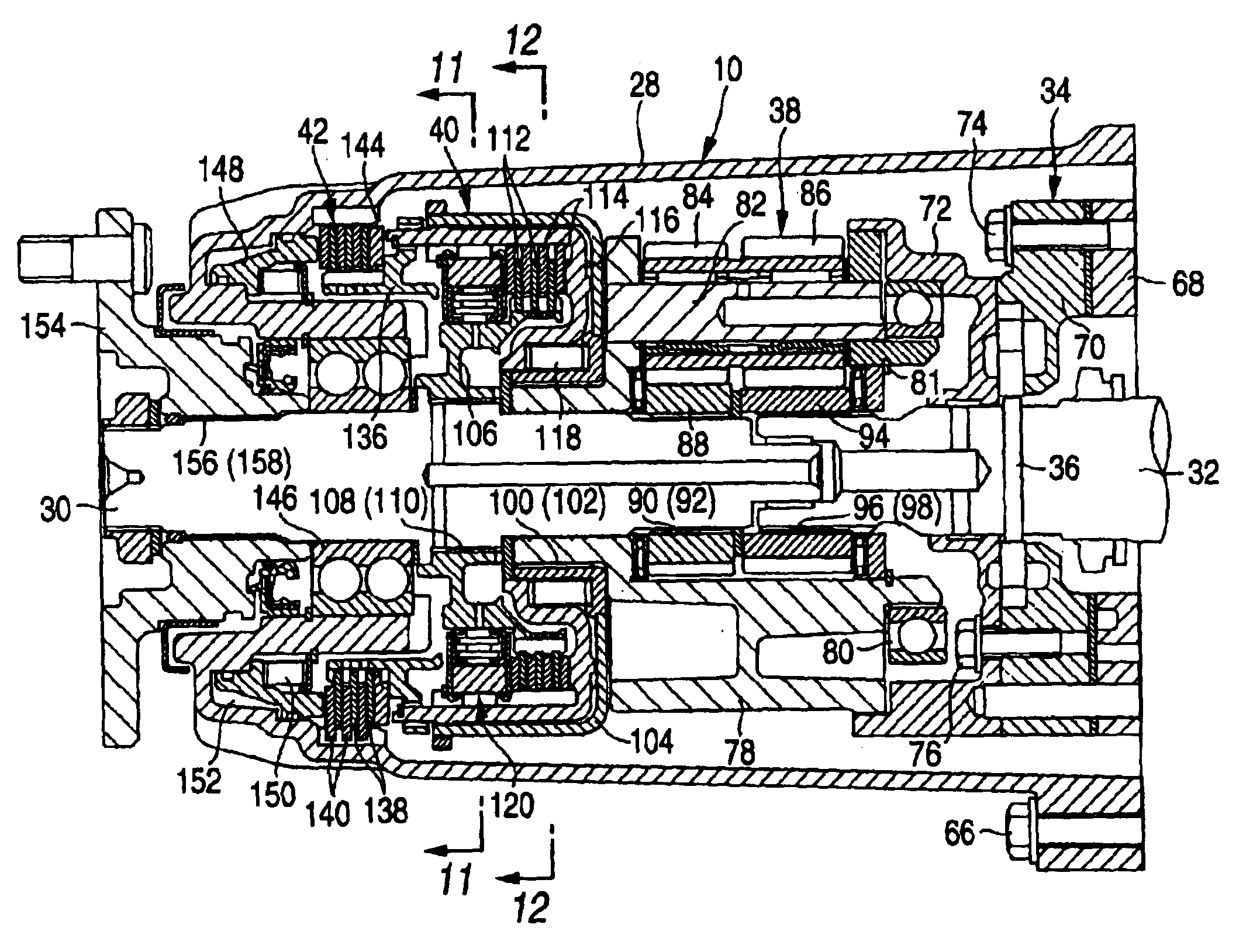
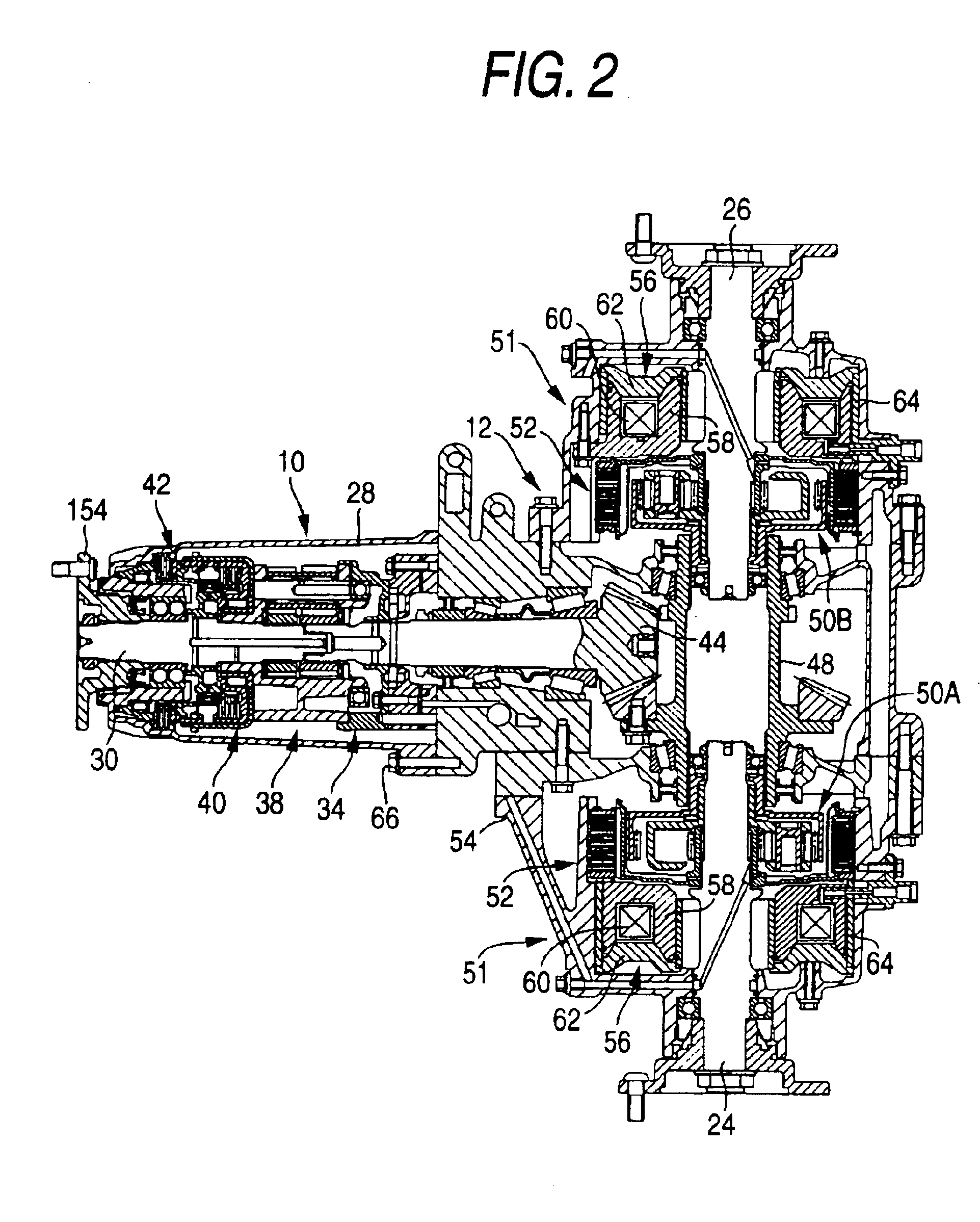
[0049]As shown in FIG. 1, a power train according to an embodiment according to the present invention mainly includes a front differential 6 and a rear differential 12 and a power transfer apparatus of the present invention. The power or drive from an engine 2 disposed at the front of the vehicle is transmitted from an output shaft 4 a of a transmission 4 to the front differential 6. A power transfer apparatus or a speed increasing apparat...


PUM


Abstract

A power transfer apparatus including a clutch having a biasing device for biasing the clutch piston in a direction in which the clutch discs engage with the clutch plates, a transmission brake disposed in line in an axial direction of the clutch, an actuator disposed in line in an axial direction of the transmission brake for disengaging the clutch at the same time of applying the transmission brake, and a planetary carrier sub-assembly disposed in line in the axial direction of the clutch, wherein the power transfer apparatus provided between an input shaft and an output shaft which are accommodated within a casing for selectively changing the speed of the output shaft.

Description

BACKGROUND OF THE INVENTION[0001]1. Field of the Invention[0002]The present invention relates to a power transfer apparatus for secondary or coupled driving wheels of a four-wheel drive vehicle.[0003]2. Description of the Related Art[0004]In conventional four-wheel drive vehicles, in turning a corner of a small turning radius at low or middle speed in a four-wheel driving mode, there is caused a difference in wheel speed between front and rear wheels which is attributed to a difference in turning radius between the front and rear wheels, resulting in the occurrence of a tight corner braking phenomenon.[0005]Front and rear wheels driving systems disclosed in JP-B-7-61779 and JP-B-7-64219 are known as related arts for solving the problem of tight corner braking phenomenon.[0006]In the front and rear wheels driving systems disclosed in the Japanese Examined Patent Publications, an average wheel speed of secondary driving wheels relative to an average wheel speed of primary driving whee...

Claims


Application Information

Patent Timeline
IPC IPC(8): B60K17/16B60K23/04B60K17/35B60K23/08F16H3/56F16H3/44B60K17/26B60K17/00B60K17/348
CPCB60K17/165B60K17/35B60K23/04B60K23/0808F16H3/56B60K17/26
Inventor IMAMURA, MASAHIRO
Owner HONDA MOTOR CO LTD
Why Eureka
Try Eureka