Self-tapping resorbable two-piece bone screw

a two-piece bone screw and self-tapping technology, applied in the field of orthopedic screws, can solve the problems of chronic irritation and inflammation of surrounding body tissue, most frequently injured, and additional surgical procedures may be required

Inactive Publication Date: 2005-07-12
ETHICON INC
View PDF74 Cites 377 Cited by
  • Summary
  • Abstract
  • Description
  • Claims
  • Application Information

AI Technical Summary

Problems solved by technology

Although the structure of the knee provides one of the strongest joints of the body, the knee is usually one of the most frequently injured joints, e.g., athletes frequently stress and tear knee ligaments.
A disadvantage of such screws is that once healing is complete, an additional surgical procedure may be required to remove the screw from the patient.
The enlarged heads on such screws can protrude from the bone tunnel and can cause chronic irritation and inflammation of surrounding body tissue.
Permanent metallic medical screws in movable joints can, in certain instances, cause abrading of ligaments during normal motion of the joint.
Screws occasionally back out after insertion, protruding into surrounding tissue and causing discomfort.
Furthermore, permanent metallic screws and fixation devices may shield the bone from beneficial stresses after healing.
Under some conditions, the stress shielding which results from the long term use of metal bone fixation devices can lead to osteoporosis.
Conventional bioabsorbable interference screws are softer and weaker than metallic compositions, such that they are not self-tapping, requiring the holes drilled into the bone to be tapped.
The necessity to tap holes in the injured bone adds to the complexity of the surgical procedure and lengthens the time required to complete the operation.
The disadvantage of this approach is that the non-absorbable fibers remain in the body tissue after the bioabsorbable polymer has been absorbed and may migrate or cause tissue inflammation.
However, lack of reinforcement-to-matrix interfacial bonding leads to poor load transfer between the reinforcement and the matrix.
The weakness of the interface is accentuated when the implants are placed in the human body and may result in compromised long-term performance.
Unfortunately, the consolidation or the melting temperature of the matrix usually causes the biocompatible organic fibers to partially relax their molecular orientation, thereby losing their strength and stiffness and adversely affecting the properties of the composite.
Thus the efforts to utilize bioabsorbable materials for orthopedic load bearing applications has not been entirely successful.

Method used


Image

  • Self-tapping resorbable two-piece bone screw
  • Self-tapping resorbable two-piece bone screw
  • Self-tapping resorbable two-piece bone screw

Examples


example 1

[0033]Three screws were made for simulation of a bone-tendon-bone ACL repair. Two of the screws were controls. The controls were monolithic in nature, i.e. composed of a single material, and of a one-piece design which incorporated all of the features of the present invention except for the means of connecting a front and rear component.

[0034]The first control was composed of poly(lactic acid), or PLA, machined from billets of PLA previously formed by injection molding. The second control was composed of a composite of 20 / 80 (volume percent) β-tricalcium phosphate (TCP) particles (10-micron average diameter) in PLA. These screws were also machined from billets of TCP / PLA composites previously formed by injection molding.

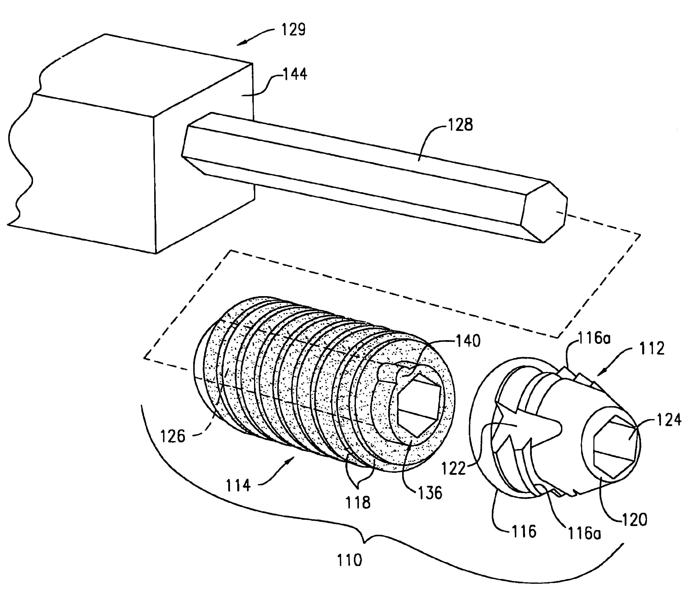
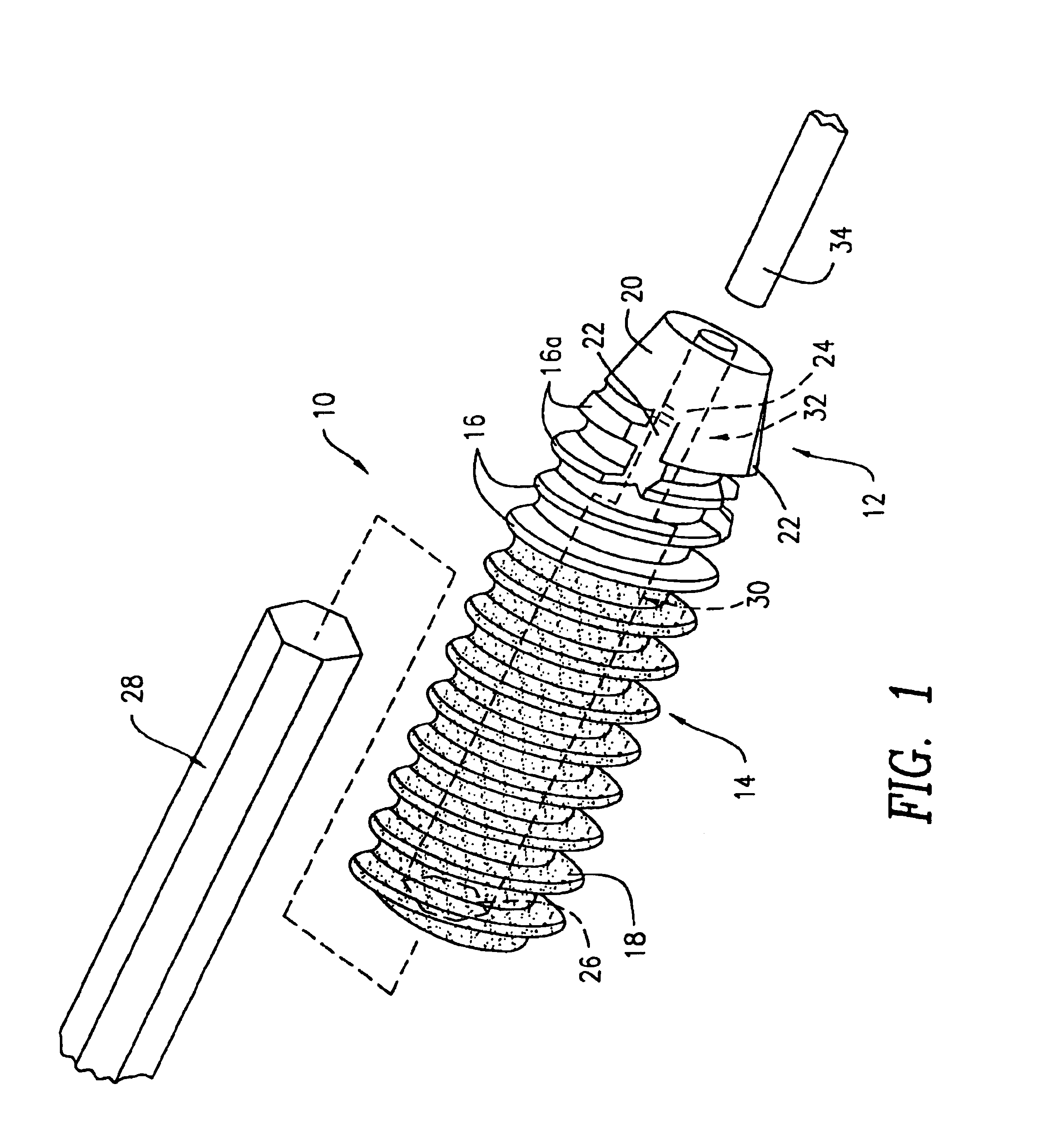
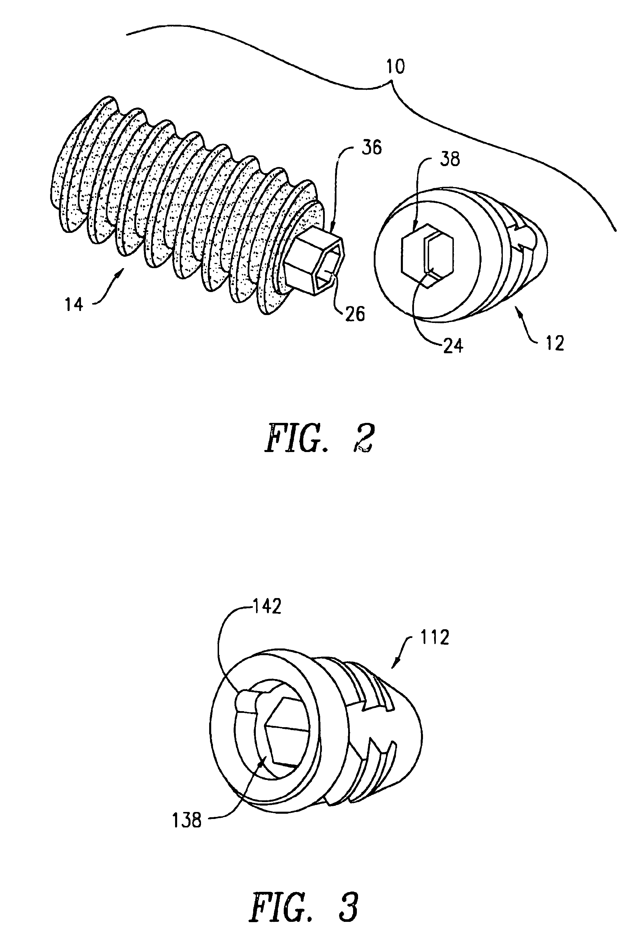
[0035]The third screw included a front and rear component. The rear component was composed of PLA machined from the same billets of PLA formed by injection molding as mentioned above. The front component was composed of metal machined from the rods of cold rolled sta...


PUM


Abstract

An orthopedic interference screw has a hard, self-threading front section and a bioabsorbable rear section. The two sections are conjoined and threaded such that the hard front section cuts threads into the bone and the softer rear section follows the threads into the bone. Preferably, the screw has an axial bore for matingly receiving a turning tool such as a hex wrench.

Description

FIELD OF THE INVENTION[0001]This invention relates to orthopedic screws and related surgical procedures using same, and, more particularly, to interference screws for securing synthetic or biological connective tissue to bone.BACKGROUND OF THE INVENTION[0002]The knee joint is one of the strongest joints in the body because of the powerful ligaments that bind the femur and tibia together. Although the structure of the knee provides one of the strongest joints of the body, the knee is usually one of the most frequently injured joints, e.g., athletes frequently stress and tear knee ligaments. The large number of ligament injuries has given rise to considerable innovative surgical procedures and devices for replacing and reconstructing torn or dislocated ligaments, typically involving grafting autografts, allografts, or a synthetic construct, to the site of a torn or dislocated ligament. For example, the replacement of an anterior cruciate ligament (ACL) may involve transplanting a port...

Claims


Application Information

Patent Timeline
Patent Type & Authority Patents(United States)
IPC IPC(8): A61B17/86A61B17/68A61F2/08A61B17/00A61B17/58
CPCA61B17/8685A61F2/0811A61B17/8635A61B17/864A61B17/8645A61B17/866A61B2017/00004A61F2/0805A61F2002/0829A61F2002/0841A61F2002/0858A61F2002/0882A61F2250/0019A61F2250/003Y10S606/909
Inventor TENHUISEN, KEVOR S.JANAS, VICTOR F.COOPER, KEVIN L.OVERAKER, DAVID W.YUAN, J. JENNY
Owner ETHICON INC
Why Eureka
Try Eureka