

Air conditioner having permanent magnet rotating electric machine
a permanent magnet, electric machine technology, applied in the direction of dynamo-electric machines, magnetic circuit rotating parts, magnetic circuit shape/form/construction, etc., can solve the problems of reducing the effective range of induced voltage, rotating electric machines are out of working order, etc., to reduce the inductance of the windings, reduce the inductance of the wirings, and reduce the magnitude of the effect of the inductan
- Summary
- Abstract
- Description
- Claims
- Application Information
AI Technical Summary
Benefits of technology
Problems solved by technology
Method used
Image

Examples
first embodiment
[0042
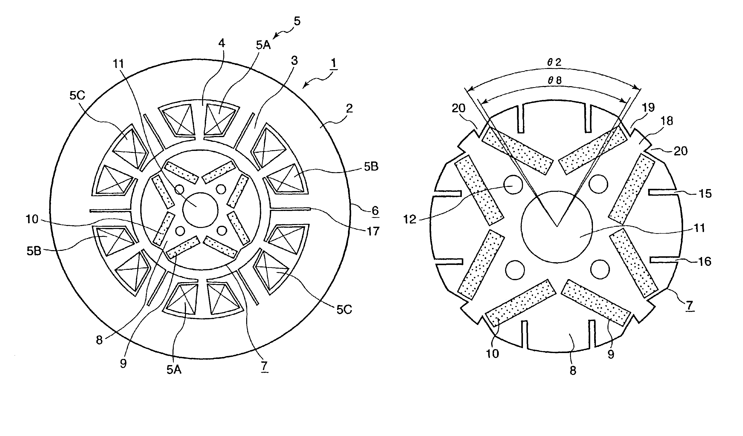
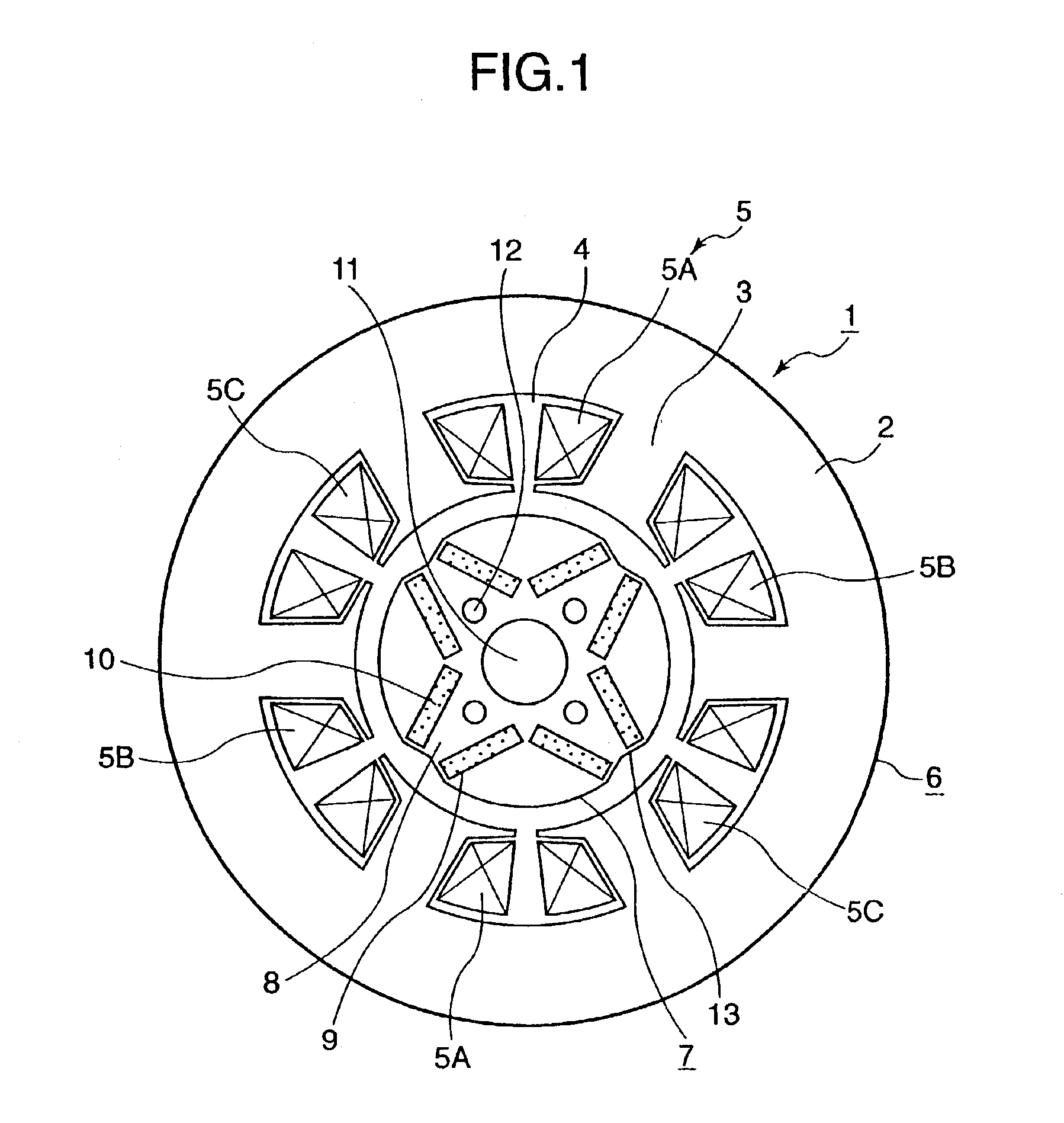
[0043]FIG. 1 is a radially sectional view of a permanent magnet rotating electric machine according to a first embodiment of the present invention. In the first embodiment, a stator 6 of a permanent magnet rotating electric machine 1 comprises a stator core 2, and armature windings 5 wound in a plurality of slots 4 that are formed in the stator core 2 together with teeth 3. The armature windings 5 include concentrated U-phase windings 5A, concentrated V-phase windings 5B, and concentrated W-phase windings 5C. The rotor 7 of the permanent magnet rotating electric machine 1 comprises a rotor core 8, and permanent magnets 10, each pair of adjacent ones of which are respectively placed in permanent magnet inserting holes 9 that are arranged like a letter “V” and formed in the rotor core 8. A shaft fitting hole 11, into which the shaft (not shown) is fitted, is formed in the rotor core 8. Incidentally, the permanent magnets 10 are arranged therein so that the first embodiment has a ...
second embodiment
[0056
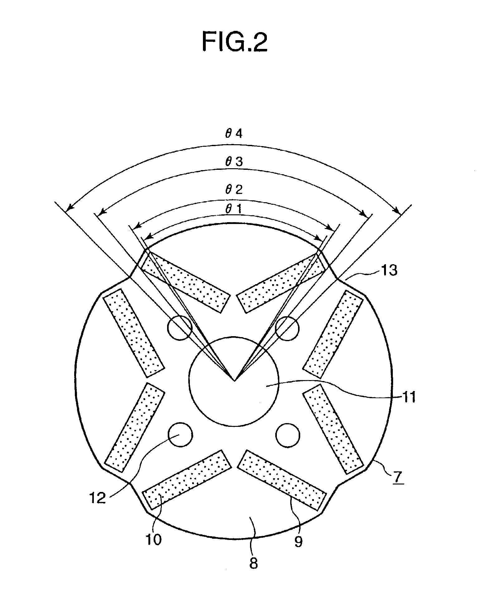
[0057]FIG. 4 is an enlarged radially sectional view of a rotor 7 of a permanent magnet rotating electric machine according to a second embodiment of the present invention. As shown in FIG. 2, the difference between the second embodiment shown in FIG. 4 and the first embodiment shown in FIG. 2 resides in that the permanent magnets 10 of the first embodiment are replaced with U-shaped permanent magnets 14 in the second embodiment.
[0058]The second embodiment have effects similar to those of the first embodiment shown in FIG. 1.
third embodiment
[0059
[0060]FIG. 5 is an enlarged radially sectional view of a rotor 7 of a permanent magnet rotating electric machine according to a third embodiment of the present invention. The third embodiment shown in FIG. 5 differs from the first embodiment shown in FIG. 2 in that slits 15 and 16 are formed at points outwardly located from the permanent magnets 10 of each pair, which are arranged like a letter “V”, so that such points are points of intersection of the outer circumference of a section of the rotor and trisectors of the angle θ4 to be trisected into angles θ5, θ6, and θ7 (that is, θ4 / 3=θ5=θ6=θ7).
[0061]In the case of the third embodiment, the armature reaction magnetic flux generated by the armature current is reduced still more, as compared with the first embodiment shaped as illustrated in FIG. 2. Thus, q-axis inductance is reduced still more. Consequently, the armature current commutation is achieved more quickly.
PUM
 Abstract
Description
Claims
Application Information