Method and apparatus generating and detecting torsional wave inspection of pipes or tubes

a technology of torsional wave and inspection method, which is applied in the direction of material magnetic variables, instruments, specific gravity measurements, etc., can solve the problems of limited device sensitivity, increased incidents of degradation, and limited ability to inspect a material in the immediate vicinity

Inactive Publication Date: 2005-07-12
SOUTHWEST RES INST
View PDF13 Cites 45 Cited by
  • Summary
  • Abstract
  • Description
  • Claims
  • Application Information

AI Technical Summary

Benefits of technology

[0024]It is yet another object of the present invention to provide a magnetostrictive sensor that is suitable for low frequency operation (200 kHz or less), has good sensitivity and long inspection range, and is relatively tolerate to liftoff.
[0026]Another object of the present invention is to provide a method and apparatus for nondestructive evaluation of pipes and tubes using magnetostrictive sensors with torsional waves that has better defect detectability particularly in liquid filled pipes or tubes.
[0028]The magnetostrictive sensors can also be used to detect defects in cylindrical structures such as to detect defects in electric resistance welding, such as in pipes that are welded along a seam thereof. For example, a magnetostrictive transmitter can be placed on one side of the pipe being investigated and a magnetostrictive receiver on the other side of the pipe. By propagating a guided wave in circumferential direction around the pipe, any defects in the pipe can immediately be detected, such as in the area of the weld. For generation and detection of the symmetrical (S) or the anti-symmetrical (A) Lamb wave mode in a plate type structure, the DC magnet or field required for MsS operation is applied parallel to the direction of wave propagation. For generation and detection of the shear horizontal (SH) wave mode, the DC magnetic field required for MsS operation is applied perpendicular to the direction of wave propagation. Due to the enclosed nature of cylindrical structures such as pipes and tubes, the shear horizontal wave can be induced to act as a torsional wave along the length of the pipe or tube. The generation of a shear horizontal or torsional wave along the length of the pipe or tube allows defect detectability that will not be hampered by the presence of liquid in the pipe or tube.
[0030]Also, a thin ferromagnetic strip that is magnetized in the circumferential direction may be wrapped around and held tightly against the pipe or tube. Thereafter, a torsional wave may be generated or detected where the ferromagnetic strips are located along the pipe or tube. The circumferential magnetization around the pipe or tube is in the ferromagnetic strip. It is very important to hold the ferromagnetic strip in tight surface contact with the pipe or tube so that the full effect of the torsional wave can be felt and detected in either the transmitter or receiver coils adjacent thereto.

Problems solved by technology

The sensitivity of the device is limited to the directing of a wavefront normal to the surface of the material under inspection and immediately back to a sensor when reflected from an opposite wall or an anomaly.
As with other eddy current methods, the ability to inspect a material is limited to the area immediately adjacent to the sensor.
Due to the aging of such facilities and the increased requirements for inspection, incidents of degradation are likely to increase.
In most instances in the past, inspections of large plate type objects (such as large aboveground storage tanks) have required either very expensive off-line inspections or statistical samplings of randomly selected local areas that are for the most part less than reliable.
It has heretofore been difficult to carry out a thorough inspection of a plate type structure, or a structure comprised of a plurality of plate type sheets of material, without high cost and long down time for the object under inspection.

Method used


Image

  • Method and apparatus generating and detecting torsional wave inspection of pipes or tubes
  • Method and apparatus generating and detecting torsional wave inspection of pipes or tubes
  • Method and apparatus generating and detecting torsional wave inspection of pipes or tubes

Examples


Embodiment Construction

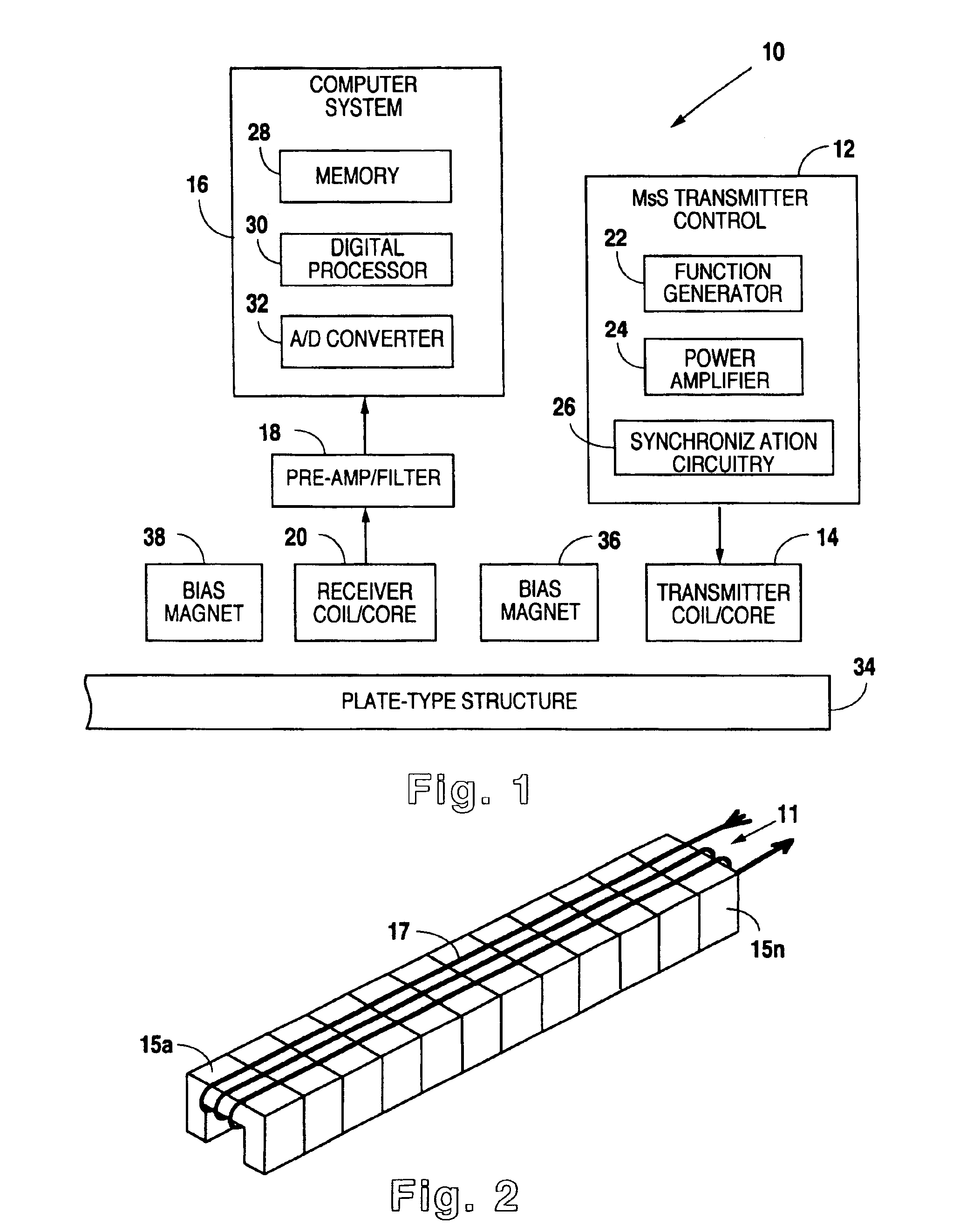
[0050]As indicated above, the present invention utilizes the basic methodological approach of earlier developed magnetostrictive sensor techniques associated with the inspection of cylindrical structures such as pipe, tubes, and the like. The basic system of such techniques is combined with a novel magnetostrictive sensor for application to plate type structures. Reference is made first to FIG. 1 for a general description of the complete system utilized to carry on the inspection of a plate type structure. Inspection system 10 includes a magnetostrictive sensor transmitter control 12 and an associated transmitter coil / core 14. Transmitter coil / core 14 is positioned adjacent to the surface of plate type structure 34. Also positioned near the surface of plate type structure 34 is receiver coil / core 20. Receiver coil / core 20 is positioned to detect reflected waves within plate type structure 34 and to thereby generate a signal representative of the wave characteristics that are reflect...


PUM

PropertyMeasurementUnit
distancesaaaaaaaaaa
lengthaaaaaaaaaa
thickaaaaaaaaaa

Abstract

A method and apparatus for implementing magnetostrictive sensor techniques for the nondestructive evaluation of pipes or tubes. A magnetostrictive sensor generates guided waves in a pipe or tube, which waves travel therethrough in a direction parallel to the longitudinal axis of the pipe or tube. This is achieved by using a magnetized ferromagnetic strip being pressed circumferentially against the pipe or tube. For improved efficiency, the strip may be made from an iron-cobalt alloy. The guided waves are generated in the strip and coupled to the pipe or tube and propagate along the length of said pipe or tube. For detection, the guided waves in the pipe or tube are coupled to the thin ferromagnetic strip and are detected by receiving MsS coils. Reflected guided waves may represent defects in the pipe or tube.

Description

[0001]This is a continuation in part patent application depending from U.S. patent application Ser. No. 09 / 815,017, filed Jul. 17, 2001 now U.S. Pat. No. 6,624,628, which is a continuation in part application depending from U.S. patent application Ser. No. 09 / 519,530 filed Feb. 25, 2000, now U.S. Pat. No. 6,294,912, which depends on Provisional Patent Application Ser. No. 60 / 124,763 filed Mar. 17, 1999, now abandoned.BACKGROUND OF THE INVENTION[0002]1. Field of the Invention[0003]The present invention relates generally to methods and devices for the nondestructive evaluation of materials. The present invention relates more specifically to a magnetostrictive sensor based system for the long range inspection of pipes and tubes made from ferromagnetic material.[0004]2. Description of the Related Art[0005]Magnetostrictive effect refers to the phenomena of a physical dimension change in ferromagnetic materials that occurs through variations in magnetization. In magnetostrictive applicati...

Claims


Application Information

Patent Timeline
Patent Type & Authority Patents(United States)
IPC IPC(8): G01N29/11G01N29/24G01N29/04
CPCG01N29/11G01N29/2412G01N2291/0421G01N2291/0422G01N2291/0428G01N2291/044G01N2291/2632G01N2291/2634
Inventor KWUN, HEGEONKIM, SANG-YOUNGCRANE, JAMES F.CHOI, MYOUNG-SEON
Owner SOUTHWEST RES INST
Why Eureka
Try Eureka