Adaptive antenna unit for mobile terminal

a mobile terminal and adaptive technology, applied in the direction of antennas, antenna details, substation equipment, etc., can solve the problems of increasing radio wave propagation loss, difficulty in increasing the cell diameter, and no longer being able to realize a mobile communication system

Inactive Publication Date: 2005-07-12
FUJITSU LTD
View PDF9 Cites 45 Cited by
  • Summary
  • Abstract
  • Description
  • Claims
  • Application Information

AI Technical Summary

Benefits of technology

[0025]Accordingly, it is a general object of the present invention to provide a novel and useful adaptive antenna unit and a mobile terminal, in which the problems described above are eliminated.

Problems solved by technology

Due to the recent progress made in semiconductor technologies related to mobile communications, it is no longer impossible to realize a mobile communication system which uses a microwave to millimeter wave band radio frequencies (RF), carries out a high-quality transmission comparable to those of fixed communication networks, and carries out a high-speed transmission on the order of several hundred MHz or greater.
However, in the mobile communication system (or cellular communication system), problems such as increased radio wave propagation loss and difficulty in increasing the cell diameter as the frequency becomes higher, and difficulty in suppressing the effects of spreading delays caused by reflection, scattering and diffraction due to buildings, mountains and the like, become more notable.
In addition, because a high-speed transmission is required and it is necessary to increase the power per bit of the high-speed data, there is a problem in that the transmission power becomes considerably large.
However, when applying the adaptive antenna technology to the mobile terminal, the conditions for the mobile terminal is much more severe than those for the base station in order to realize reduced size and weight, reduced power consumption and reduced cost of the mobile terminal.

Method used


Image

  • Adaptive antenna unit for mobile terminal
  • Adaptive antenna unit for mobile terminal
  • Adaptive antenna unit for mobile terminal

Examples


first embodiment

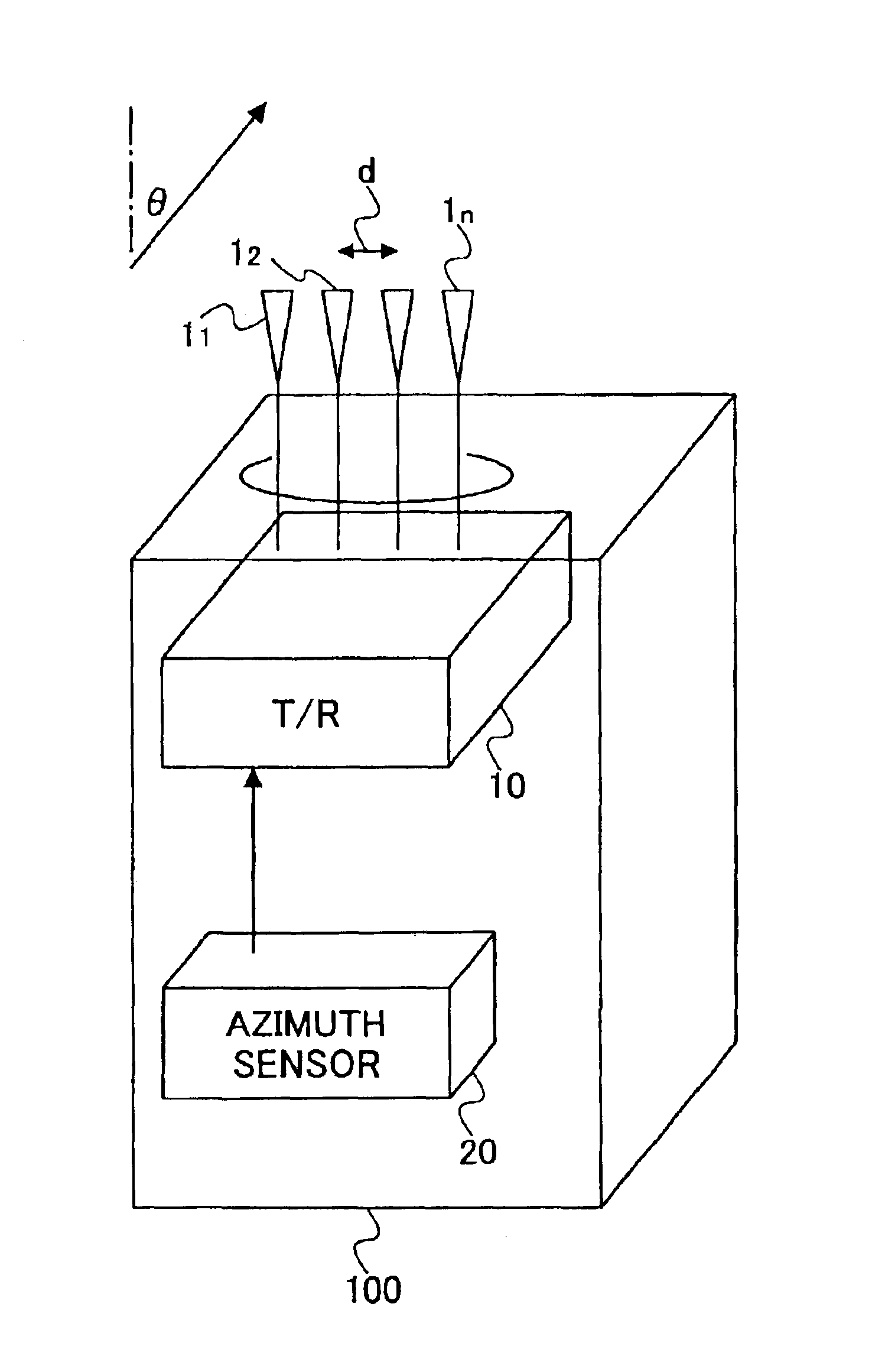
[0048]FIG. 6 is a diagram showing a basic structure of an adaptive antenna unit according to the present invention. The adaptive antenna unit is applied to a mobile terminal (or mobile station) 100 and includes an array antenna which is made up of a plurality of antenna elements 11 through 1n, a transmitter-receiver section 10 which has a function of controlling a directivity of the array antenna, and an azimuth sensor 20 which detects an azimuth or inclination of the mobile terminal. In this embodiment, the antenna elements 11 through 1n are arranged linearly on the same plane.

second embodiment

[0049]FIG. 7 is a diagram showing a basic structure of the adaptive antenna unit according to the present invention. In FIG. 7, those parts which are the same as those corresponding parts in FIG. 6 are designated by the same reference numerals, and a description thereof will be omitted. In this embodiment, the antenna elements 11 through 1n of a mobile terminal 101 are arranged in an arc, so that a beam is more easily formed within the plane in which the antenna elements 11 through 1n are arranged when compared to the arrangement shown in FIG. 1.

[0050]Of course, the number of antenna elements is not limited to four in each of the first and second embodiments shown in FIGS. 6 and 7, and the number of antenna elements may be set to an arbitrary number greater than or equal to two.

[0051]By giving a phase weighting with respect to each of the antenna elements 11 through 1n which is different for the transmission and the reception, it is possible to arbitrarily control the directivity of...

third embodiment

[0058]FIG. 8 is a diagram showing a basic structure of the adaptive antenna unit according to the present invention. The adaptive antenna unit is applied to a mobile terminal 102 and includes an array antenna which is made up of m×n planar antenna elements 111,1 through 11m,n, a transmitter-receiver section 10 which has a function of controlling a directivity of the array antenna, and an azimuth sensor 20 which detects an azimuth or inclination of the mobile terminal. In this embodiment, the planar antenna elements 111,1 through 11m,n are arranged in a matrix arrangement on the same plane.


PUM


Abstract

An adaptive antenna unit is adapted to a mobile terminal for making mobile communication and adaptively forms an antenna directivity in a direction of a base station which exchanges signals with the mobile terminal. The adaptive antenna unit is provided with an azimuth sensor to detect at least one of rotation, inclination and present position of the mobile terminal, a transmitter-receiver section to control the antenna directivity in a direction in which a reception characteristic improves based on reception signals received from a plurality of antenna elements forming the antenna directivity, and a mechanism for correcting the antenna directivity in the direction of the base station, based on the at least one of rotation, inclination and present position of the mobile terminal detected by the azimuth sensor.

Description

BACKGROUND OF THE INVENTION[0001]This application claims the benefit of a Japanese Patent Application No. 2002-164563 filed Jun. 5, 2002, in the Japanese Patent Office, the disclosure of which is hereby incorporated by reference.[0002]1. Field of the Invention[0003]The present invention generally relates to adaptive antenna units, and more particularly to an adaptive antenna unit for a mobile terminal, which adaptively controls an antenna directivity in a direction of a base station which transmits and receives signals with the mobile terminal. The present invention also relates to a mobile terminal which uses such an adaptive antenna unit.[0004]2. Description of the Related Art[0005]Recently, mobile (or wireless) communications are becoming increasingly popular. As a result, transmission techniques, including transmission techniques which use microwave bands, transmission techniques having a large transmission capacity, and transmission techniques capable of suppressing interferenc...

Claims


Application Information

Patent Timeline
Patent Type & Authority Patents(United States)
IPC IPC(8): H01Q3/26H01Q1/24
CPCH01Q1/241H01Q3/2605
Inventor IIDA, ATSUOTODA, TAKESHI
Owner FUJITSU LTD
Why Eureka
Try Eureka