
Fully automatic rapid microscope slide scanner

a slide scanner and fully automatic technology, applied in the field of optical microscopy, can solve the problems of limiting the practical utility of images, taking a long time, consuming a lot of equipment, and consuming a lot of resources,

Inactive Publication Date: 2005-07-12
LEICA BIOSYST IMAGING
View PDF8 Cites 173 Cited by
  • Summary
  • Abstract
  • Description
  • Claims
  • Application Information

AI Technical Summary

Problems solved by technology

One of the inherent limitations of optical microscopy is the tradeoff between the field of view, the portion of the sample that can be viewed through the eyepieces of a microscope, and the magnification at which the sample can be viewed.
The field of view limitation of optical microscopy requires that the microscopist manually scan a slide at low magnification to obtain an overall view of the sample or specimen.
Because it is based on image tiling, the BLISS system suffers from several known disadvantages of the image tiling approach.
For example, a first disadvantage of the BLISS system is that it takes a long time, typically twenty minutes or longer to acquire the tiled data structures.
A major cause of relative motion is the settling time of the mechanical positioning stage after issuing sequential stop and go commands.
The slow capture times of tiling systems, including the BLISS system, limits the practical utility of image tiling to a two-step process, with extensive manual intervention between the capture of an initial very low magnification macro image and the subsequent selection of small areas for higher magnification capture.
The slow acquisition time associated with tiling systems leads to a second disadvantage of the BLISS system, that being the need for manual intervention during the process of creating the tiled data structure.
For example, it would not be practical, because of acquisition time considerations, to use the BLISS system to scan an entire microscope slide at 20× magnification.
However, at the BLISS system's very low magnification of 1.25×, only 64 image tiles are needed to create a macro-image of a two inch by one inch area of a microscope slide.
Understanding now that the acquisition time limitations of any image tiling system require the capture of a very low magnification macro-image, followed by the interactive selection from this macro image of small areas to be captured at higher magnification, a third disadvantage of the BLISS system becomes apparent.
This third disadvantage resides in the realization that locating areas of interest from a very low magnification macro-image is practically limited to samples in which anatomic reference information is available.
The BLISS system thus has limited utility for non-histological samples such as Pap smears, because such cytological samples inherently lack any information about anatomic orientation.
However, as described previously, the long acquisition times required by the image tiling method make this alternative virtually impractical.
Stated differently, without manual intervention to define specific and significantly smaller areas of the microscope slide for image tiling at higher magnifications, an impossibility for cytological samples, a tiling approach has limited utility.
A fourth disadvantage of the BLISS system is its complexity and expense.
The multiple automated elements of the BLISS system represent a complicated system that, in spite of its extensive automation, may be difficult to operate and maintain.
Inherent in the cost disadvantage of the BLISS system are several limitations of any microscope slide scanning system that is based on a conventional microscope.
The most expensive component of the BLISS system is the automated microscope itself.
Microscopy becomes very labor intensive when large portions of a sample, or even the entire sample, must be manually scanned at low resolutions, typically 10× to 20×, in order to identify specific areas of interest for subsequent higher resolution interrogation.
Extended manual screening or continued viewing of a single field causes eyestrain, fatigue, and visual habituation that can negatively affect productivity and accuracy.
Another common problem associated with manual scanning of microscope slides is that portions of a slide are easily missed during manual x / y scanning of a slide.
Relocation to previously identified cells can be difficult, especially after the slide has been removed from the microscope.

Method used


Image

  • Fully automatic rapid microscope slide scanner
  • Fully automatic rapid microscope slide scanner
  • Fully automatic rapid microscope slide scanner

Examples


second embodiment

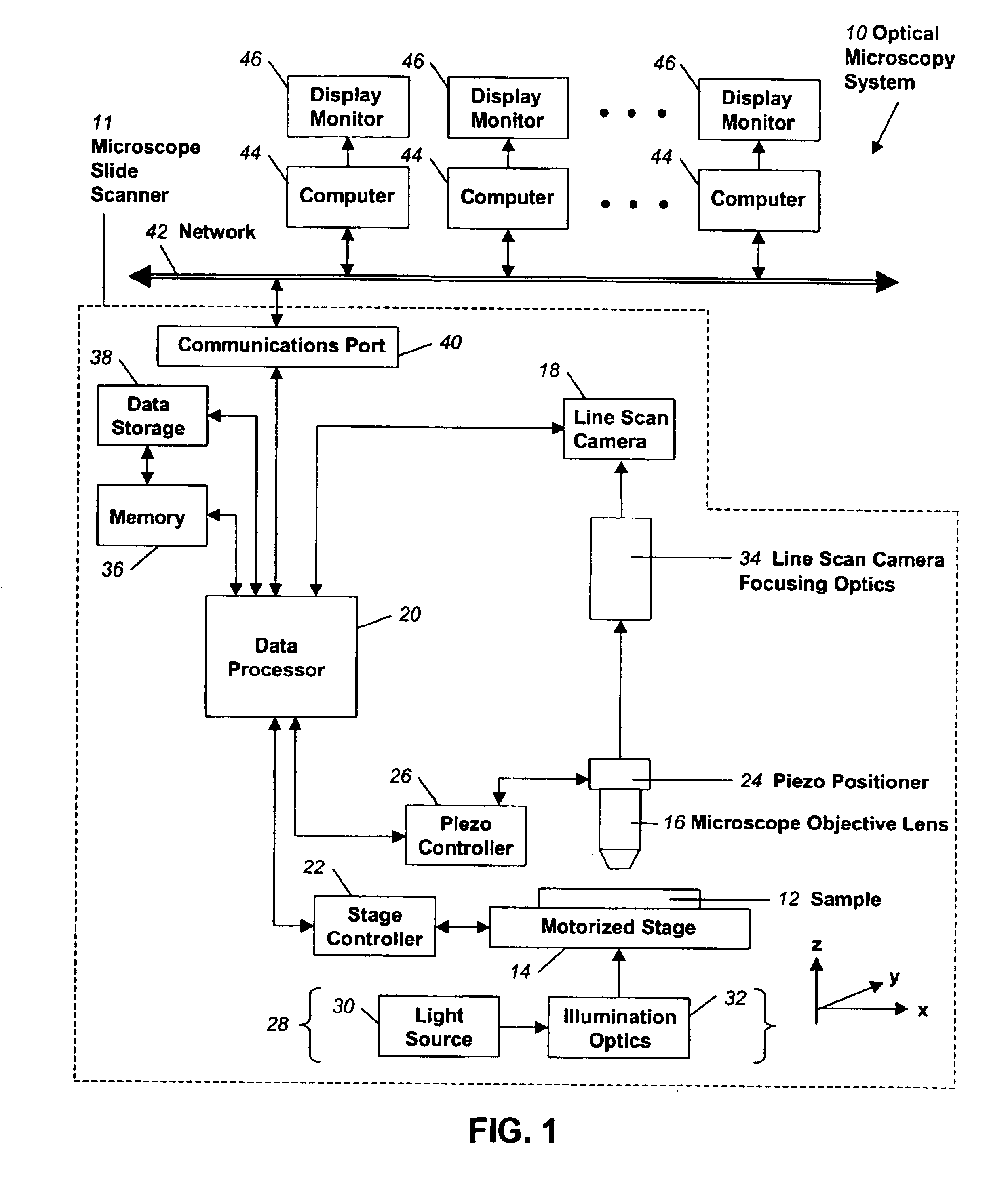
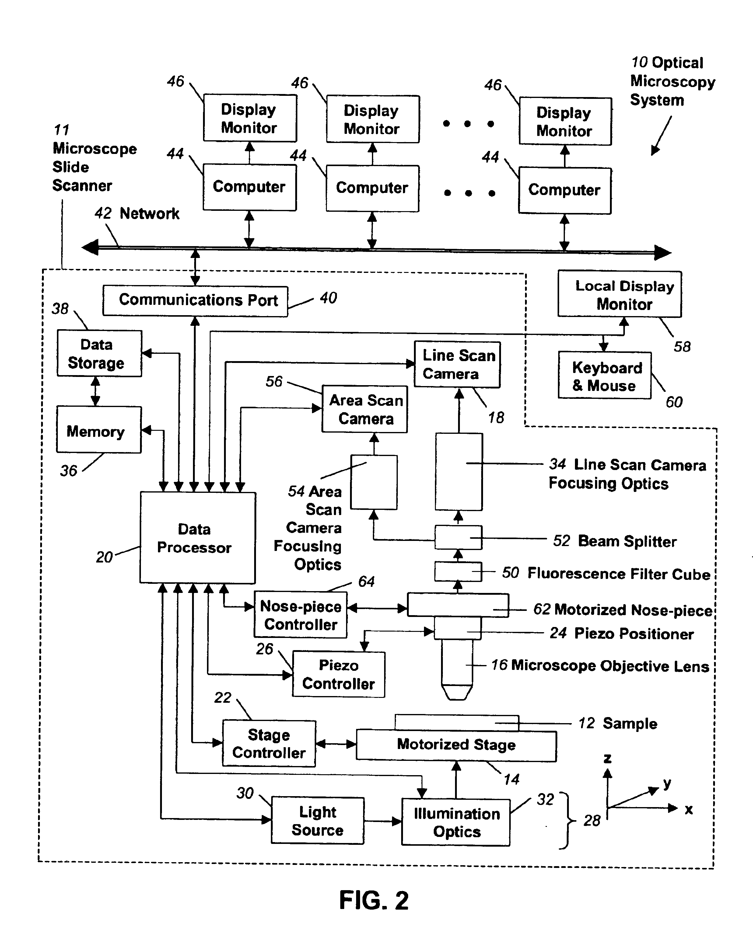
[0047]Turning now to FIG. 2, a block diagram of an optical microscopy system 10 according to the present invention is shown. In this system 10, the scanner 11 is more complex and expensive than the currently preferred embodiment shown in FIG. 1. The additional attributes of the scanner 11 that are shown do not all have to be present for any alternate embodiment to function correctly. FIG. 2 is intended to provide a reasonable example of additional features and capabilities that could be incorporated into the scanner 11.

[0048]The alternate embodiment of FIG. 2 provides for a much greater level of automation than the presently preferred embodiment of FIG. 1. A more complete level of automation of the illumination system 28 is achieved by connections between the data processor 20 and both the light source 30 and the illumination optics 32 of the illumination system 28. The connection to the light source 30 may control the voltage, or current, in an open or closed loop fashion, in order...


PUM

PropertyMeasurementUnit
perimeteraaaaaaaaaa
widthaaaaaaaaaa
acquisition timeaaaaaaaaaa

Abstract

Apparatus for and method of fully automatic rapid scanning and digitizing of an entire microscope sample, or a substantially large portion of a microscope sample, using a linear array detector synchronized with a positioning stage that is part of a computer controlled microscope slide scanner. The invention provides a method for composing the image strips obtained from successive scans of the sample into a single contiguous digital image. The invention also provides a method for statically displaying sub-regions of this large digital image at different magnifications, together with a reduced magnification macro-image of the entire sample. The invention further provides a method for dynamically displaying, with or without operator interaction, portions of the contiguous digital image. In one preferred embodiment of the invention, all elements of the scanner are part of a single-enclosure that has a primary connection to the Internet or to a local intranet. In this embodiment, the preferred sample type is a microscope slide and the illumination and imaging optics are consistent with transmission mode optics optimized for diffraction-limited digital imaging.

Description

RELATED APPLICATION[0001]The present application is a continuation application of U.S. patent application Ser. No. 09 / 563,437 filed May 3, 2000, now U.S. Pat. No. 6,711,283.BACKGROUND[0002]1. Field of the Invention[0003]The present invention relates generally to the field of optical microscopy and pertains more specifically to a fully automatic rapid microscope slide scanner.[0004]2. Related Art[0005]One of the inherent limitations of optical microscopy is the tradeoff between the field of view, the portion of the sample that can be viewed through the eyepieces of a microscope, and the magnification at which the sample can be viewed. While higher magnification microscope objective lenses with higher numerical apertures (NA) provide the microscopist with an enlarged and often higher resolution image, the field of view decreases dramatically with increases in magnification, in proportion to the square of the magnification. Even at very low magnifications such as 1.25 times (1.25×), on...

Claims


Application Information

Patent Timeline
Patent Type & Authority Patents(United States)
IPC IPC(8): G02B21/00G02B21/24G02B21/26G02B21/32G02B21/36G01N21/17G06T1/00G21K7/00H04N1/04
CPCG02B21/002G02B21/26G02B21/32G02B21/34G02B21/365G02B21/367H04N7/18H04N5/23206H04N7/183G02B21/245H04N1/053H04N1/1903H04N1/193H04N1/19573H04N23/661H04N23/631H04N23/635H04N23/56G02B21/0036G02B21/008G02B21/14H04N2201/04727H04N2201/04755
Inventor SOENKSEN, DIRK G.
Owner LEICA BIOSYST IMAGING
Learn More