Calibration of multiple cameras for a turntable-based 3D scanner

a 3d scanner and turntable technology, applied in the field of scanners, can solve the problems of difficult to supply all necessary camera parameters, difficult to derive complete mathematical models, and difficult to generate high complexity models, etc., and achieve the effects of reducing the number of cameras, and reducing the number of scanners

Inactive Publication Date: 2005-07-12
MITSUBISHI ELECTRIC RES LAB INC
View PDF3 Cites 111 Cited by
  • Summary
  • Abstract
  • Description
  • Claims
  • Application Information

AI Technical Summary

Benefits of technology

[0016]A dependency of the results on the global 3D geometry of the calibration object is avoided, becau

Problems solved by technology

Due to many limitations and incomplete information about the physical objects to be modeled, it is very difficult to derive complete mathematical models and supply all necessary camera parameters.
Generating high complexity models is therefore tedious and extremely time-consuming.
Systems which use laser scanning and range sensing hardware to generate 3D information from an object are very expensive and therefore inaccessible to most people.
In addition, the complex hardware is difficult to repair or replace.
Laser scanner methods and systems are also intrusive.
The color map from laser systems is also

Method used


Image

  • Calibration of multiple cameras for a turntable-based 3D scanner
  • Calibration of multiple cameras for a turntable-based 3D scanner
  • Calibration of multiple cameras for a turntable-based 3D scanner

Examples


Embodiment Construction

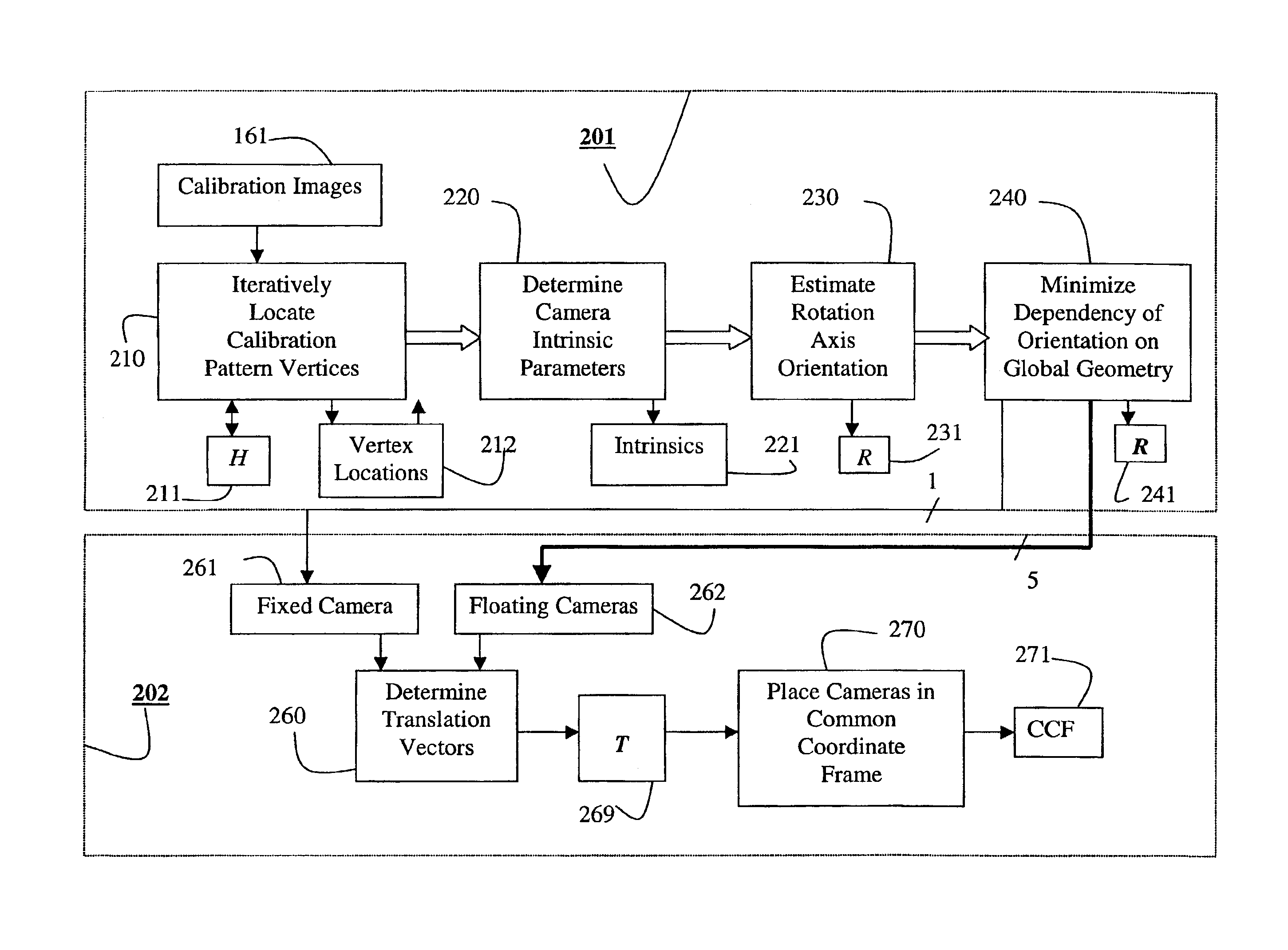
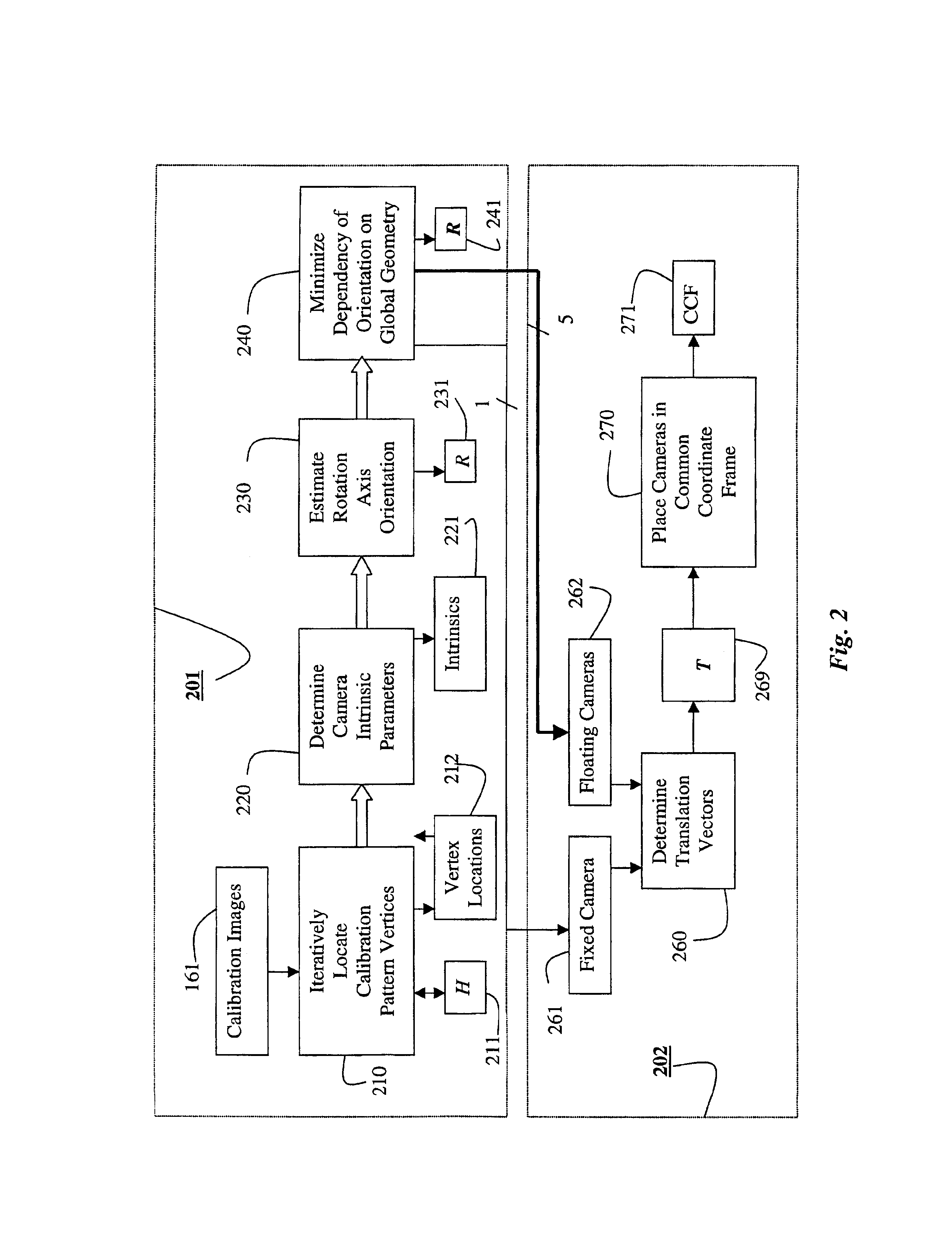
[0020]The invention provides a system and method for calibrating multiple cameras used with a turntable-based 3D scanner. The invention obtains accurate camera positions relative to a rotation axis of the turntable. Hence, camera positions relative to the turntable can be generated for any specified degree of rotation. Given these camera positions, and corresponding images of a physical object on the turntable, it is possible to acquire a 3D model of that object.

[0021]The present invention deals with the calibration process, i.e., a full metric calibration, obtaining the intrinsic and extrinsic parameters of the multiple cameras, and an axis of rotation of the turntable in an Euclidean coordinate frame. After, the system has been calibrated, models of objects can be constructed by the scanner.

System Structure

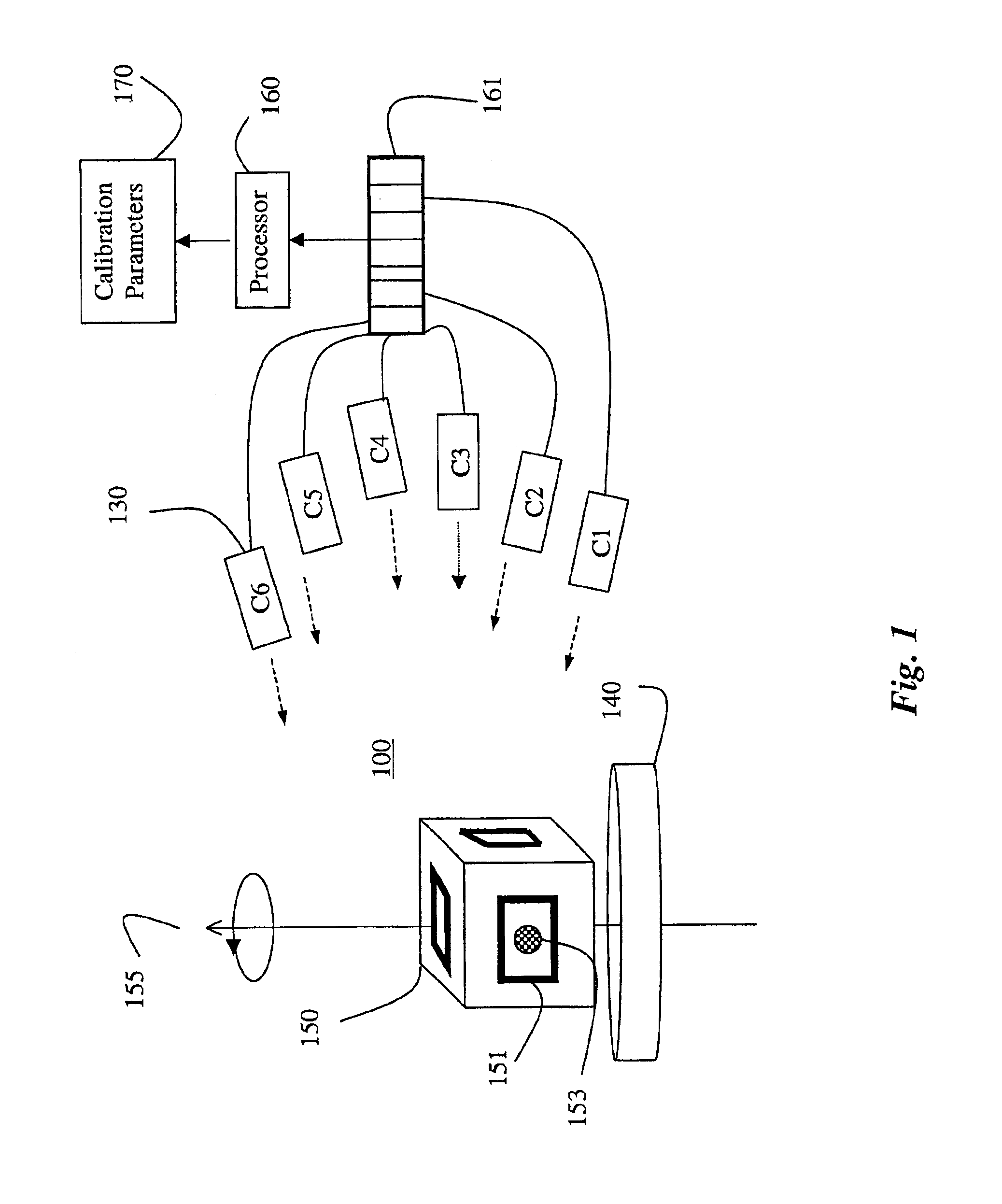
[0022]FIG. 1 shows a system 100 for calibration of multiple cameras according to the invention. The system 100 includes multiple cameras (C1-C6) 130, and a turntable 140. A proc...


PUM


Abstract

In a method and system for calibrating a multiple cameras, a calibration object is placed on a turntable while a set of images is acquired with each camera while rotating the turntable. Vertices of a calibration pattern are located in each set of images, and intrinsic parameters for each camera are determined from the vertices. An orientation of a rotation axis of the turntable relative to a position of each camera is estimated from the intrinsic parameters of each camera. A dependency of each orientation on a global geometry of the calibration pattern is minimized. Then, one camera is selected as a fixed camera, all other cameras are designated as floating cameras. A translation vector between the fixed camera and each floating camera is determined, and the translation vectors are used to place the cameras in a common coordinate frame according to the translating vectors.

Description

FIELD OF THE INVENTION[0001]This invention relates generally to calibrating scanners, and more particularly to calibrating multiple cameras for a turntable-based 3D scanner system.BACKGROUND OF THE INVENTION[0002]Many computer graphics systems require realistic three-dimensional models to render arbitrary, realistic but synthetic scenes. The models can be used for animation, solid modeling, visualization, robotics, games, scientific studies, CAD / CAM, and multimedia. In computer graphics systems, three-dimensional rendering software and graphics luminance models typically display three-dimensional models.[0003]Due to many limitations and incomplete information about the physical objects to be modeled, it is very difficult to derive complete mathematical models and supply all necessary camera parameters. Generating high complexity models is therefore tedious and extremely time-consuming.[0004]Systems which use laser scanning and range sensing hardware to generate 3D information from a...

Claims


Application Information

Patent Timeline
IPC IPC(8): G06T7/00G01B11/00G06T1/00H04N13/02
CPCG06T7/002G06T7/85
Inventor BEARDSLEY, PAUL
Owner MITSUBISHI ELECTRIC RES LAB INC
Why Eureka
Try Eureka