Image processing apparatus and method and storage medium

a technology of image processing and storage medium, which is applied in the direction of color television with bandwidth reduction, television systems, instruments, etc., can solve the problems of not meeting all the requirements of users, jbig system does not execute encoding, and system for compressing multi-value images and binary images as mentioned above, so as to achieve efficient compression and high picture quality

Inactive Publication Date: 2005-07-12
CANON KK
View PDF7 Cites 43 Cited by
  • Summary
  • Abstract
  • Description
  • Claims
  • Application Information

AI Technical Summary

Benefits of technology

[0014]The invention is made in consideration of the above conventional systems and it is a main object of the invention to provide a new system which can efficiently compress and can keep a high picture quality for any one of a multivalue image and a binary image.
[0021]According to the invention, still another object of the invention is to efficiently entropy encoding block division information which is generated by a block division processing as an element technique of the new image encoding system.

Problems solved by technology

According to the conventional JPEG system and JBIG system, all images of multivalue images (photograph or the like) and binary images (character image, diagram image, or the like) cannot be efficiently compressed without deteriorating a picture quality.
On the other hand, the JBIG system does not execute the encoding on a block unit basis.
However, the system for compressing the multivalue image and binary image as mentioned above does not satisfy all of the requirements of the user yet.

Method used


Image

  • Image processing apparatus and method and storage medium
  • Image processing apparatus and method and storage medium
  • Image processing apparatus and method and storage medium

Examples


first embodiment

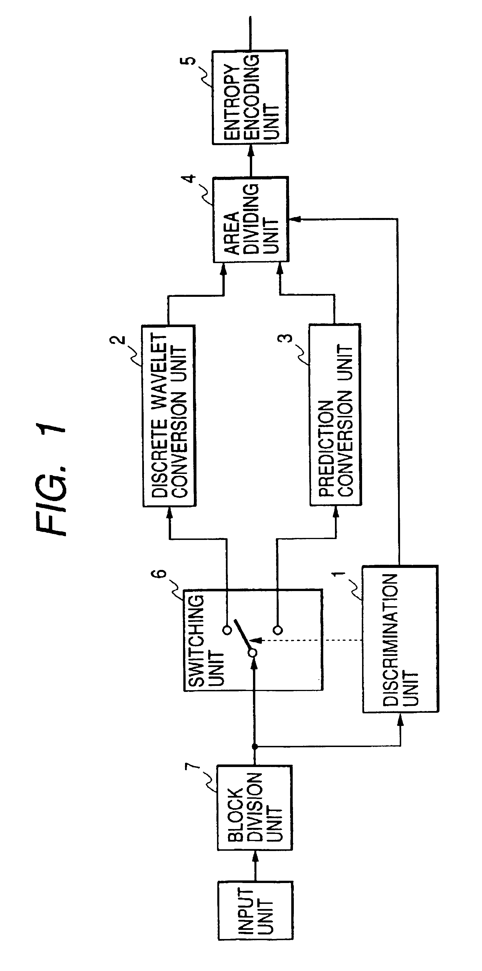
[0046]FIG. 1 is a schematic diagram of an image processing apparatus which is used in the invention.

[0047]A flow of processes of each unit will be first simply explained.

[0048]In the diagram, image data which is inputted from an input unit in the diagram is multivalue image data having a predetermined number of bits per pixel.

[0049]In the embodiment, it is assumed that not only image data showing a photograph, a picture, or the like suitable for multivalue expression but also image data showing characters, diagram, or the like to be inherently expressed by a binary value is included in the multivalue image data having a depth of 8 bits per pixel.

[0050]In the embodiment, therefore, to efficiently encode image data showing an image in which those images mixedly exist, the former image is encoded as multivalue image data and the latter image is encoded as binary image data, thereby improving an encoding efficiency.

[0051]Subsequently, the inputted multivalue image data is supplied to a ...

third embodiment

[0203]the invention will now be described hereinbelow with reference to the drawings.

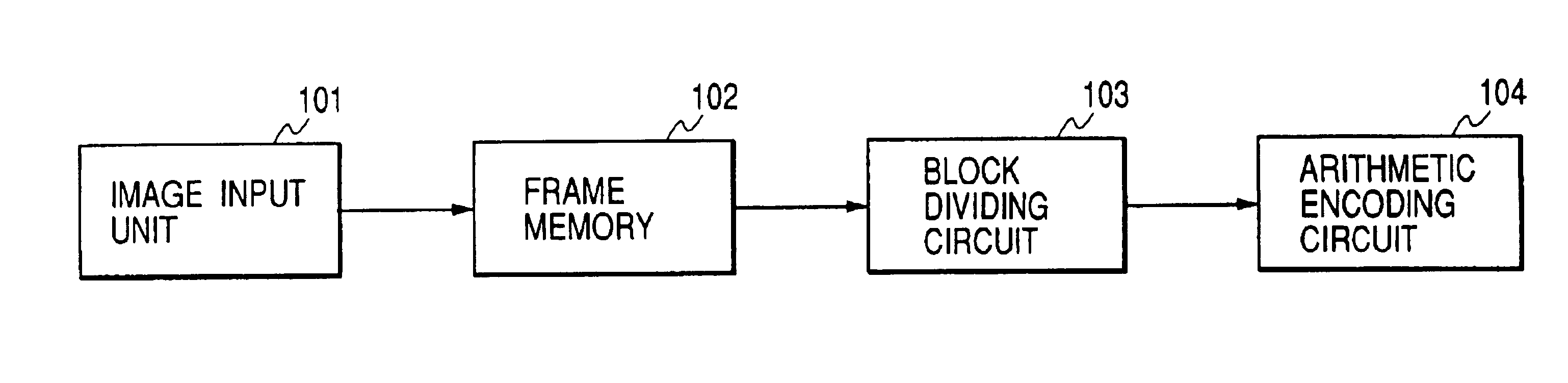
[0204]FIG. 13 shows an image processing apparatus to execute the third embodiment of the invention. In the diagram, reference numeral 101 denotes an image input unit; 102 a frame memory to store the whole image (picture plane) to be encoded; 103 a block dividing circuit; and 104 an arithmetic encoding circuit.

[0205]In the embodiment, what is called a binary image such that “0” assumes a pixel value of a background and “1” assumes a pixel value of a foreground is encoded.

[0206]The operation of each unit in the embodiment will now be described in detail hereinbelow.

[0207]First, all of the pixel data (1 or 0) showing the image (corresponding to one picture plane) as an encoding target is sequentially inputted from an image input unit in accordance with the raster scanning order and is stored into the frame memory 102.

[0208]The image input unit is, for example, an image pickup apparatus such as scanner,...

fourth embodiment

[0283]The invention is not limited to the foregoing embodiments. For example, in the fourth embodiment, although the filter of two taps has been used in the discrete wavelet conversion, another filter of a larger number of taps can be also used. Although the QM-Coder has been used as an arithmetic encoding method, another arithmetic encoding such as Q-Coder, CJ-Coder, or the like can be also used.

[0284]The system for entropy encoding the intermediate code is not limited to the arithmetic encoding. For example, a Huffman encoding such that the method is switched in accordance with the status or the like can be also used.

[0285]Although the third embodiment has been described on the assumption that an image of one picture plane to be encoded is a mere binary image, the invention is not limited to it. That is, the invention also incorporates a case where it is applied when position information of one picture plane showing the position “1” of a photograph area and the position “0” of a c...


PUM


Abstract

A system which can efficiently compress any one of a multivalue image and a binary image and can preferably keep a high picture quality is provided. To accomplish this object, the system has means for generating conversion coefficients of M values by converting input image data by a first system, means for generating conversion coefficients of N values (N>M) by converting the input image data by a second system and means for outputting first information showing a position where a significant conversion coefficient exists in a block constructed by the conversion coefficients of M values or the conversion coefficients of N values and second information showing the significant conversion coefficient. Block division information which is generated by a block dividing process as an element technique of the image encoding system is efficiently entropy encoded. To accomplish it, the system has means for outputting division information showing whether each of a plurality of blocks including an encoding subject block has further been divided into a plurality of blocks or not and means for entropy encoding the division information corresponding to the encoding subject block on the basis of a presumption probability according to a division situation of a neighboring block of the encoding subject block.

Description

BACKGROUND OF THE INVENTION[0001]1. Field of the Invention[0002]The invention relates to image processing apparatus and method for efficiently compressing an image and to a storing medium in which such a method has been stored.[0003]2. Related Background Art[0004]In recent years, computers and networks have remarkably been developed and various information such as character data, image data, audio data, and the like are handled in a computer and in a network.[0005]With respect to the image data and audio data, data of a relatively large data amount is often handled. Therefore, a process to reduce the data amount by compressing the image data and audio data has been performed hitherto.[0006]For example, by compressing the image data, a large quantity of image information can be transmitted through a network at a high speed.[0007]According to the above image compressing technique, a system (generally called a JPEG) for compressing a multivalue still image in the ITU-T Recommendation T...

Claims


Application Information

Patent Timeline
Patent Type & Authority Patents(United States)
IPC IPC(8): H04N7/26H04N19/60H03M7/30H04N1/41H04N19/423H04N19/46H04N19/63H04N19/70H04N19/88H04N19/91
CPCH04N19/70H04N19/63H04N19/186H04N19/1883H04N19/64H04N19/36
Inventor KAJIWARA, HIROSHISATO, MAKOTOKISHI, HIROKI
Owner CANON KK
Why Eureka
Try Eureka