Method and apparatus for selection and use of optimal antennas in wireless systems

a wireless system and optimal antenna technology, applied in the field of wireless system optimal antenna selection and use, can solve the problems of increasing system cost, limiting the applicability of such a strategy, and rf (radio frequency chain) chains are much more expensive than antenna elements, so as to achieve the best performance of wireless link, improve performance, and benefit economic

Inactive Publication Date: 2005-07-12
THE BOARD OF TRUSTEES OF THE LELAND STANFORD JUNIOR UNIV
View PDF11 Cites 68 Cited by
  • Summary
  • Abstract
  • Description
  • Claims
  • Application Information

AI Technical Summary

Benefits of technology

[0011]According to the present invention it might be advantageous economically (or from the perspective of improved performance) to use a small number of RF chains and a large number of antennas and connect the RF chains to a selected set of optimal antennas that provide the best performance of the wireless link. One of the basic goals of selecting the optimal set of antennas is to optimize the wireless link being used according to a predetermined criterion including any one of capacity, diversity, spatial multiplexing or any other criteria for which the wireless link is to be used.

Problems solved by technology

Although increasing the number of antennas for transmitting and / or receiving in a wireless system improves the performance of a wireless link, there are some limitations on the applicability of such a strategy.
RF (Radio-frequency) chains (transmitter RF chains in particular) are much more expensive than the antenna elements.
Thus, increasing the number of antennas in such systems would in effect increase the cost of the system.

Method used


Image

  • Method and apparatus for selection and use of optimal antennas in wireless systems
  • Method and apparatus for selection and use of optimal antennas in wireless systems
  • Method and apparatus for selection and use of optimal antennas in wireless systems

Examples


Embodiment Construction

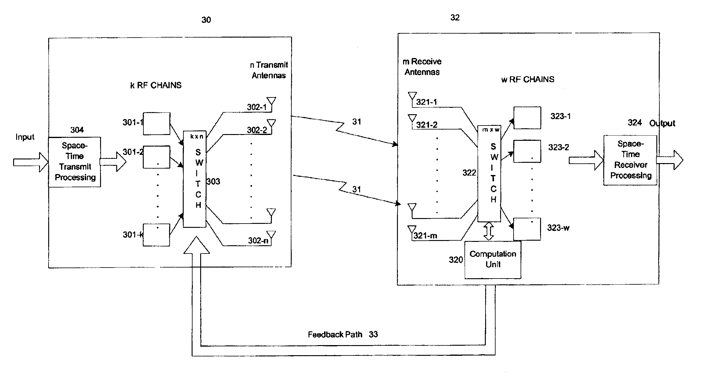
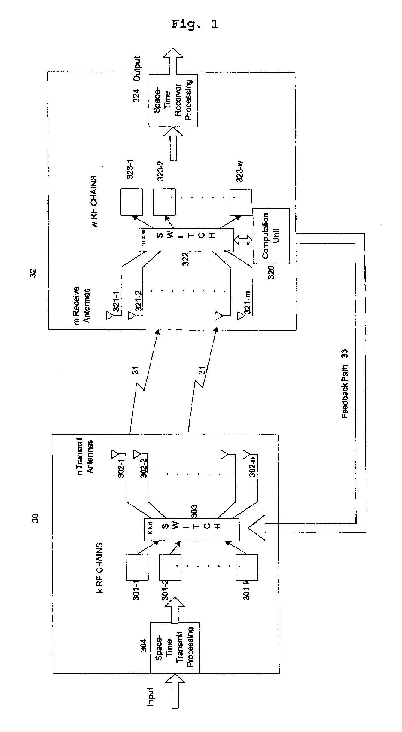
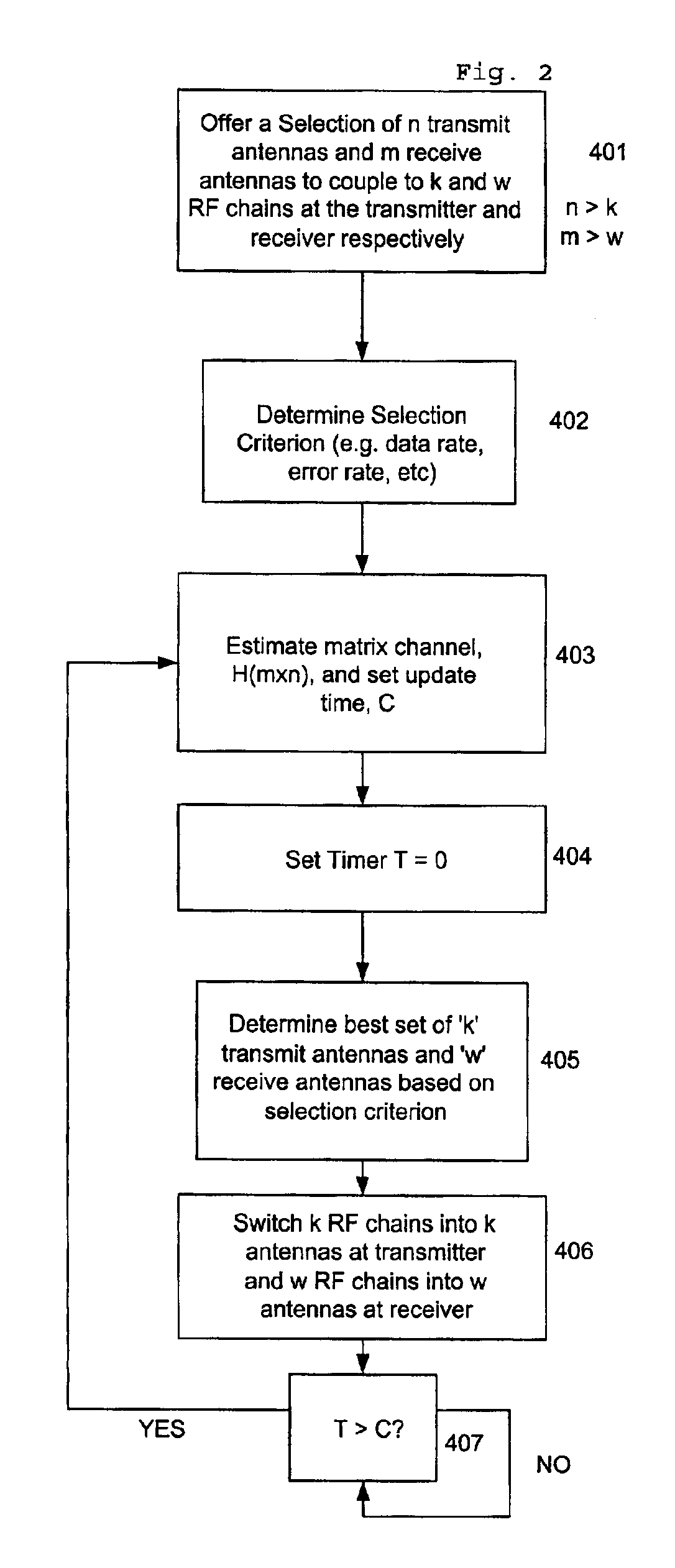
[0015]The present invention will be described with respect to FIGS. 1 and 2. However, it should be noted that the present configuration as illustrated in FIGS. 1 and 2 is representative of an embodiment of the present invention. The present invention is not limited to the embodiment illustrated herein. The present invention can be implemented according to any number of embodiments with the primary feature being the selection of an optimal set of antennas from a plurality of antennas wherein the optimal set of antennas corresponds to the number of transmit and / or receive RF chains having a number less than or equal to the number of antennas.

[0016]The present invention is intended to operate in a wireless system with multiple antennas at the transmitter and / or receiver. Particularly, the invention provides a method and apparatus for use in a system having a plurality of antennas for transmitting and / or receiving wireless signals over a wireless link. According to the present invention...


PUM


Abstract

A method and apparatus for selecting an optimal set of antennas from a plurality of antennas for use by a transmitter and / or receiver having a plurality of RF chains to transmit and / or receive a wireless signal on a wireless link. According to the invention information concerning transmission of wireless signals on the wireless link is determined and an optimal set of antennas from the plurality of antennas is selected based on the information. Thereafter, the RF chains are connected to the optimal set of antennas to permit transmission and / or reception of the wireless signal from the RF chains on the wireless link via the optimal set of antennas. The RF chains correspond in number to the number of antennas in the optimal set of antennas, and the number of antennas included in the plurality of antennas is greater than the number of RF chains.

Description

BACKGROUND OF THE INVENTION[0001]The present invention relates to a method and apparatus for transmitting and receiving information across a wireless link using a plurality of antennas. More particularly, the present invention relates to a method and apparatus for selecting an optimal set of antennas from a plurality of antennas for use by a transmitter and / or receiver for improving any performance criterion (such as data rate, error rate, etc) over a wireless link.[0002]Current wireless systems generally use single antennas at the transmitter and receiver. For a broad class of wireless systems including mobile and satellite communications, personal communication and wireless network systems, system performance, such as data rate, error rate, etc., can be improved substantially by the use of multiple antennas at the transmitter and / or the receiver.[0003]Different approaches and concerns in implementing such multiple antenna systems are, for example, described in “On Limits of Wirele...

Claims


Application Information

Patent Timeline
Patent Type & Authority Patents(United States)
IPC IPC(8): H04B7/04H04B7/06H04B7/08
CPCH04B7/0691H04B7/0874H04B7/061H04B7/0639H04B7/0673
Inventor GORE, DHANANJAY A.NABAR, ROHIT U.PAULRAJ, AROGYASWAMISANDHU, SUMEET
Owner THE BOARD OF TRUSTEES OF THE LELAND STANFORD JUNIOR UNIV
Why Eureka
Try Eureka