Coding system and decoding system
- Summary
- Abstract
- Description
- Claims
- Application Information
AI Technical Summary
Benefits of technology
Problems solved by technology
Method used
Image
Examples
first preferred embodiment
(First Preferred Embodiment)
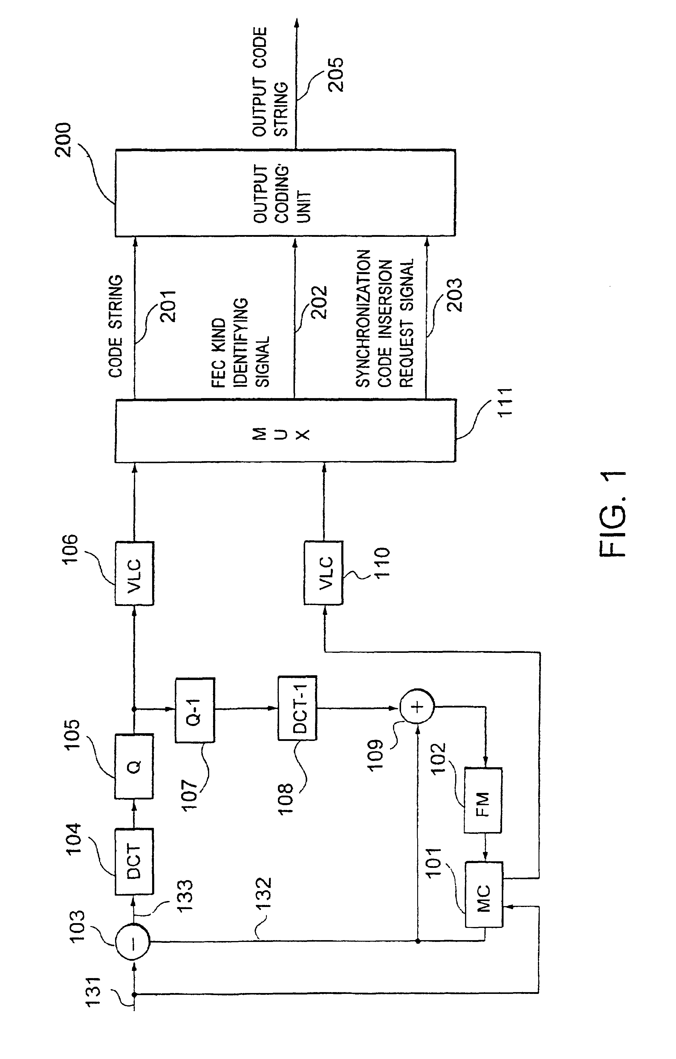
[0094]FIG. 1 is a block diagram of the first preferred embodiment of a dynamic image coding system, according to the present invention, wherein a coding system having an error correcting / detecting code switching function of the present invention is combined with a high-efficiency compression coding system which uses a motion-compensated adaptive prediction and a discrete cosine transform coding serving as a kind of an orthogonal transform coding. A coding system comprising the combination of a motion-compensated adaptive prediction and a discrete cosine coding is detailed in, e.g., Literature 1 “International Standard of Multimedia Coding” by Hiroshi Yasuda, Maruzen (June 1991). Therefore, only the operation of the coding system will be schematically described. In addition, it is assumed that information bits are separated from detection bits in an error correcting / detecting code similar to a BCH code.
[0095]In FIG. 1, with respect to an input dynamic imag...
second preferred embodiment
(Second Preferred Embodiment)
[0150]Referring to FIGS. 12 through 14, the second preferred embodiment of the present invention will be described below.
[0151]In this preferred embodiment, a dynamic image coding system and a dynamic image decoding system can surely detect synchronization even if a code string is transmit-ted / stored in a transmission line / storage medium in which the number of bits is decreased due to the loss of a part of a bit string or the number of bits is increased due to the addition of excessive bits.
[0152]FIG. 12 is a block diagram showing the principle of a process for detecting synchronization when such addition- / loss of bits occurs. It is assumed herein that the right synchronization code comprises “0”s of sync—0_len bits and a “1” of one bit as shown in FIG. 12(a). Furthermore, in FIG. 12, “x” denotes a bit other than a synchronization code.
[0153]FIGS. 12(b) through 12(e) show how the synchronization code is changed by the addition / loss of bits. It is assumed...
third preferred embodiment
(Third Preferred Embodiment)
[0181]The third preferred embodiment of the present invention will be described below. In this preferred embodiment, the error correcting / detecting code is not used. At this point, this preferred embodiment is different from the first and second preferred embodiments.
[0182]FIG. 18 is a block diagram of a dynamic image coding system in this preferred embodiment. Using the same reference numbers as those in FIG. 1 for the parts corresponding to those in FIG. 1, the different points from the first preferred embodiment will be mainly described. In this preferred embodiment, the construction and operation of an output coding unit 200 are different. In addition, although the basic operation of a multiplexer 111 is the same as the multiplexer 111 of FIG. 1, the multiplexer 111 in this preferred embodiment outputs only a multiplexed code string 201 and a synchronization code insertion request signal 203 since the error correcting- / detecting code is not used.
[0183...
PUM
 Abstract
Description
Claims
Application Information
 - R&D
- Intellectual Property
- Life Sciences
- Materials
- Tech Scout
- Unparalleled Data Quality
- Higher Quality Content
- 60% Fewer Hallucinations
Browse by: Latest US Patents, China's latest patents, Technical Efficacy Thesaurus, Application Domain, Technology Topic, Popular Technical Reports.
© 2025 PatSnap. All rights reserved.Legal|Privacy policy|Modern Slavery Act Transparency Statement|Sitemap|About US| Contact US: help@patsnap.com


