
Method and apparatus for deploying airbags

a technology of airbags and airbags, applied in child seats, instruments, tractor parts, etc., can solve the problems of 8,000 deaths, side impact problems that are considerably more difficult to solve in this way, and related deaths

Inactive Publication Date: 2005-07-19
AMERICAN VEHICULAR SCI
View PDF73 Cites 25 Cited by
  • Summary
  • Abstract
  • Description
  • Claims
  • Application Information

AI Technical Summary

Benefits of technology

[0028]It is an object of the present invention to provide a new and improved apparatus and method for deploying multiple airbags in a vehicle wherein at least one airbag is provided to inflate and cause the occupant to be moved into a better position for subsequent deployment of another, protective airbag.
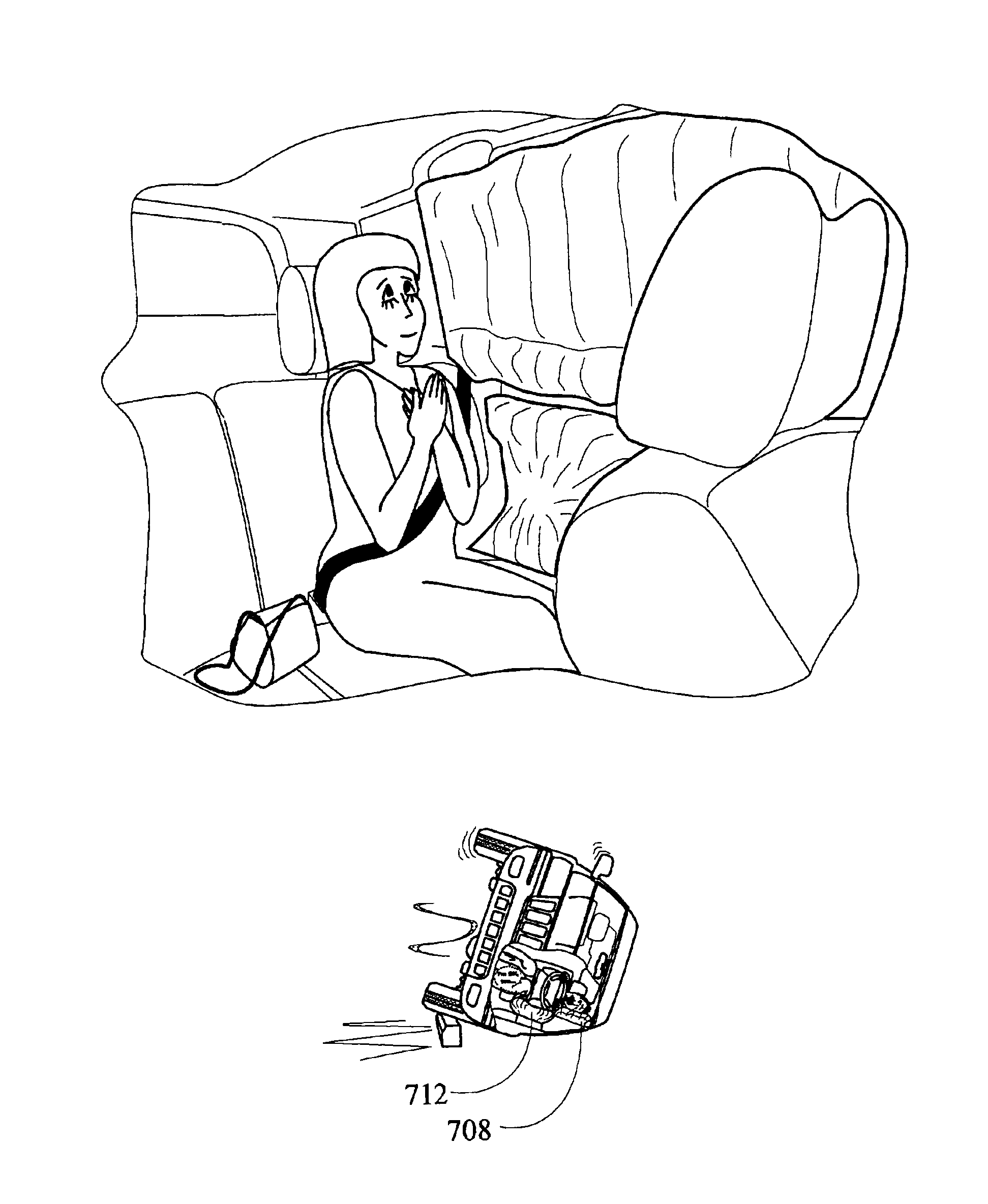
[0029]It is another object of the present invention to provide a new and improved apparatus and method for deploying airbags during a rollover in order to prevent injury to an occupant.
[0030]It is yet another object of the present invention to provide a new and improved apparatus and method for deploying airbags in particular during a rollover, but also for other types of crashes, in order to prevent an occupant from being positioned on the externally-facing side of a deploying side curtain airbag.
[0032]1. To provide for the enhanced protection of occupants in side impacts by determining the probable severity of a pending accident and inflating an airbag prior to the impact to displace the occupant away from the vehicle door.
[0047]16. To provide a single airbag module for protection of the head and torso of an occupant in side impacts.
[0049]18. To provide a structure and method for enabling movement of the occupant and his seat in the event of a side, front or rear impact accident to increase the space between the occupant and the intruding object.

Problems solved by technology

Side impacts were the second cause of automobile related deaths with about 8,000 fatalities each year.
The side impact problem is considerably more difficult to solve in this way than the frontal impact problem due to the lack of space between the occupant and the side door and to the significant intrusion of the side door into the passenger compartment which typically accompanies a side impact.
In addition, the human body is more vulnerable to side impacts than frontal impacts and there is usually significant intrusion into the passenger compartment.
Sensors used for side impact airbags, however, usually begin sensing the crash only at the beginning of the impact at which time there is insufficient time remaining to move the occupant before he is impacted by the intruding door.
Even if the airbag were inflated instantaneously, it is still not possible to move the occupant to create the desired space without causing serious injury to the occupant.
The problem is that the sensor that starts sensing the crash when the impact has begun, is already too late, i.e., once the sensor detects the crash, it is usually too late to properly inflate the airbag.
Prior to 1994, this was not practical due to the inability to predict the severity of the accident prior to the impact.
Further, it was not possible to differentiate between these different accidents with a high degree of certainty.
Once a sufficiently large airbag is deployed in a side impact and the driver displaced away from the door and the steering wheel, he will no longer be able to control the vehicle that could in itself cause a serious accident.
Anticipatory sensors have heretofore not been used because of their inability to predict the severity of the accident.
Karr et al. is limited to frontal crashes and rear crashes and does not appear to even remotely relate to side impacts.

Method used


Image

  • Method and apparatus for deploying airbags
  • Method and apparatus for deploying airbags
  • Method and apparatus for deploying airbags

Examples


Embodiment Construction

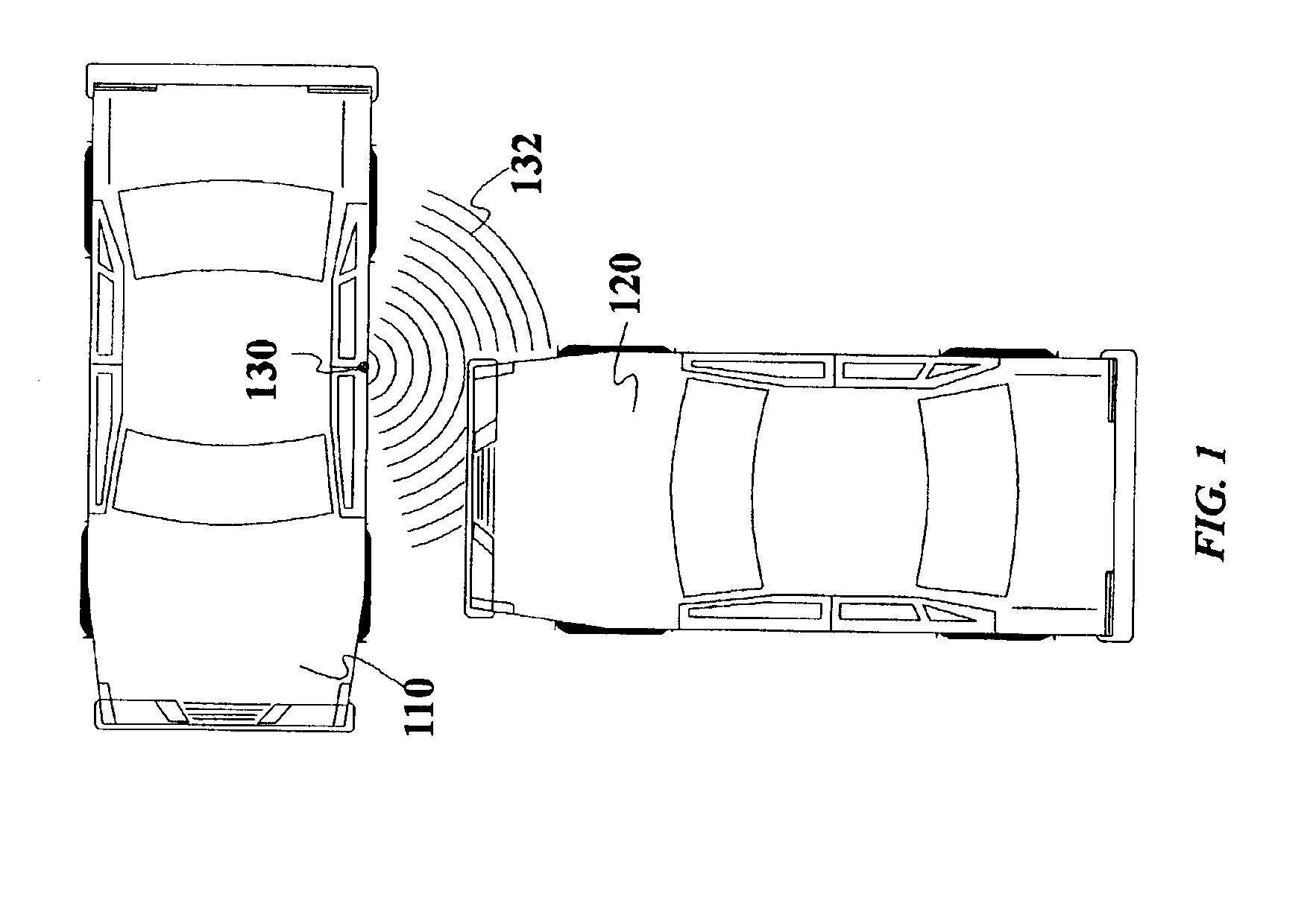
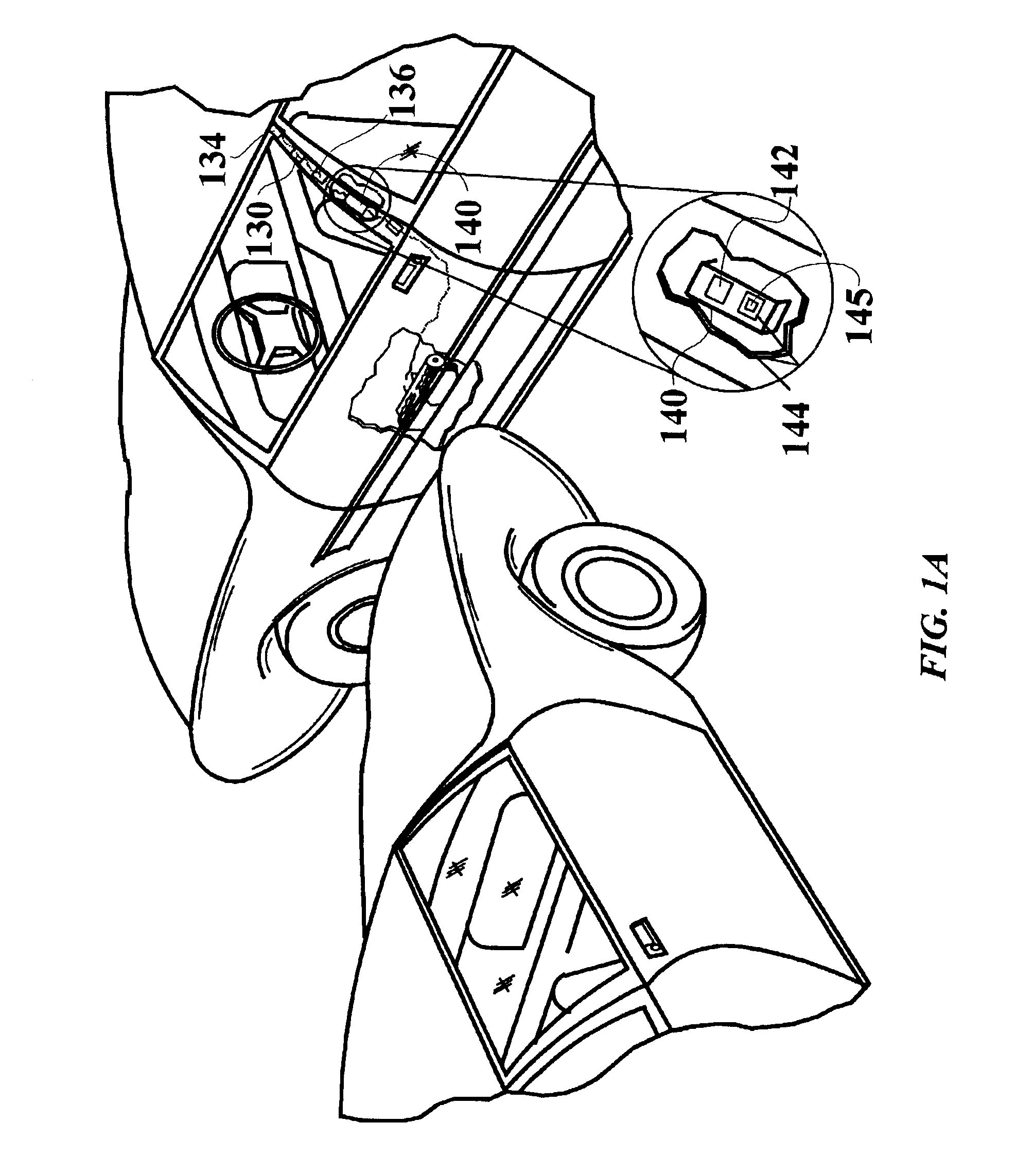
[0108]Referring to the accompanying drawings wherein like reference numerals refer to the same or similar elements, FIG. 1 is an overhead view of a vehicle 110 about to be impacted in the side by an approaching vehicle 120 where vehicle 110 is equipped with an anticipatory sensor system in accordance with the invention including a wave transmitter 130 which transmits waves 132 toward the approaching vehicle 120. A perspective view of vehicle 110 is shown in FIG. 1A and illustrates the transmitter 130 connected to an electronic module 140 (this connection being symbolized by the dotted lines between the transmitter 130 and the module 140 which may represent a wire). Module 140 is mounted in the B-pillar and contains circuitry means 142 to drive the transmitter 130 to transmit waves and circuitry means 144 coupled to wave receivers 134,136, which receive the returned waves and convert the same into signals, to process the signals from receivers 134 and 136 representative of the return...


PUM


Abstract

Apparatus and method for deploying airbags in a vehicle in which a first inflatable airbag protects an occupant in a seating location during a crash and a second inflatable airbag moves the occupant in the seating location away from an interior surface of the vehicle upon inflation. A crash sensor system determines that a crash involving the vehicle will occur or is occurring and initiates inflation of the first and second airbags. The second airbag may be inflated prior to inflation of the first airbag such that inflation of the second airbag causes the occupant to be moved away from the interior surface of the vehicle and into a better position for deployment of the first airbag. In one exemplary embodiment, the first airbag is a side curtain airbag and the second airbag is arranged in a door of the vehicle to move the occupant away from the door.

Description

CROSS REFERENCE TO RELATED APPLICATIONS[0001]This application is a continuation-in-part of U.S. patent application Ser. No. 10 / 097,082 filed Mar. 13, 2002 which in turn is a continuation-in-part of U.S. patent application Ser. No. 09 / 825,173 filed Apr. 3, 2001 now U.S. Pat. No. 6,623,033 which in turn is:[0002]1) a continuation-in-part of U.S. patent application Ser. No. 09 / 024,085 filed Feb. 17, 1998, now U.S. Pat. No. 6,209,909, which is a continuation-in-part of U.S. patent application Ser. No. 08 / 247,760 filed May 23, 1994 now abandoned ; and[0003]2) a continuation-in-part of U.S. patent application Ser. No. 09 / 307,883 filed May 10, 1999, now U.S. Pat. No. 6,343,810, which is also a continuation-in-part of the '085 application. These applications are incorporated by reference herein in their entirety.[0004]This application is related to, on the grounds that it includes common subject matter, U.S. patent application Ser. No. 10 / 097,086 filed Mar. 13, 2002.FIELD OF THE INVENTION[0...

Claims


Application Information

Patent Timeline
IPC IPC(8): B60N2/00B60N2/26B60N2/02B60R22/32B60R22/26B60R21/01B60R21/16B60N2/28B60R19/42B60R19/20B60R19/02B60R19/18G01S17/88G01S13/00G01S15/88G01S15/00G01S13/88G01S15/87G01S7/02G01S17/00G01S7/48G01S7/41G08G1/16B60R21/00B60R21/26G01S17/89G01S7/539G01S7/487B60R21/0132B60R21/0134B60R21/21B60R21/233
CPCB60N2/002B60N2/0232B60N2/0276B60N2/28B60N2/2806B60N2/2863B60R19/205B60R19/42B60R21/013B60R21/23138B60R21/233B60R22/26B60R22/321B60R25/25G01S7/417G01S7/4802G01S13/88G01S15/87G01S15/88G01S17/88G08G1/161G08G1/163G08G1/164B60N2002/0268B60R21/0132B60R21/0134B60R2021/0006B60R2021/23332B60R2021/26058B60W2550/402G01S7/48G01S7/487G01S7/539G01S17/89B60N2002/0272B60R21/01332B60W2556/50B60N2/0272B60N2/0268B60N2/02246B60N2/0025B60N2210/40B60N2/0027B60N2220/20
Inventor BREED, DAVID S.
Owner AMERICAN VEHICULAR SCI
Learn More