
Medical device for intraluminal endovascular stenting

a technology of endovascular stenting and medical devices, which is applied in the field of intraluminal endovascular stenting, can solve the problems of stent radial enlargement, difficulty in crossing a narrow lesion, and interference with the ability to crimp the stent onto the catheter, so as to prevent the shortening of the stent and promote longitudinal flexibility

Inactive Publication Date: 2005-07-19
MEDTRONIC INC
View PDF65 Cites 141 Cited by
  • Summary
  • Abstract
  • Description
  • Claims
  • Application Information

AI Technical Summary

Benefits of technology

[0010]These and other objects are accomplished by the present invention. The medical device of the present invention includes a catheter and a stent mounted on the catheter, the stent having a hollow, cylindrical body made with a plurality of rings. The rings each extend circumferentially around the cylindrical body and include an undulating series of peaks and valleys. Typically, the undulating peaks and valleys of the rings are formed by opposing curved segments joined to each other by substantially straight segments. The rings are joined together by a series of links which are shaped and arranged to promote longitudinal flexibility as the stent is delivered on the catheter and effective scaffolding after deployment and to prevent shortening of the stent as the stent is expanded.
[0012]Another aspect of the invention is the conformal nesting of ring and link components such that the stent can be readily crimped onto a balloon or other expansion device on the catheter. The stent made according to the present invention may be made from a tube which is cut with lasers or other techniques which are well known to those skilled in the art. The initial pattern cut into the tube includes link and ring components which cooperate with each other but which provide sufficient spacing between components that the stent can be crimped onto a catheter without causing general abutment of the ring and link components with each other and also permit longitudinal movement of the link components without disturbing the crimp of the ring components on the catheter during deployment of the stent through tortuous coronary arteries. The need for spacing between the components in the crimped condition must be balanced with the need to provide improved scaffolding of the vessel being treated. A relatively abundant number of links provides improved scaffolding of the vessel but potentially interferes with the ability to crimp the stent onto the catheter. In the present invention, the inflection points can provide the spacing needed for the nesting of the ring and link components by extending the ring in a generally circumferential direction for a distance which is sufficient to accommodate the width of the link component and provide space needed between the link components and the ring components which allows the stent to be crimped onto the catheter. In some embodiments of the invention, each inflection point includes an attachment to two connecting links extending in opposing directions and the circumferential offset at the inflection point provides for nesting of both connecting links with the ring components on the opposite sides. Thus, in the present invention, large numbers of connecting links can be included within a crimpable stent design.
[0013]Another aspect of the invention is to provide flexibility in the stent crimped on the catheter such that the stent can flex near the inflection points without significant radial expansion as the stent is subjected to bending along a longitudinal axis as it is advanced through bends in a coronary artery. As stents are advanced through tortuosities of a vessel, they are subjected to bending forces which can produce longitudinal stresses on the connector links. If the movement of connector links pulls the undulations open from their crimped position, the stent can become radially enlarged and have difficulty in crossing a narrow lesion. The present invention reduces the potential for this problem by aligning the connection of the links with the rings at a short, circumferentially extending portion, by providing curvature in the links which are then able to flex and thereby reduce stress on the junctions between the rings and the links and by providing “dead end” connections with the links which then avoids the transmission of forces from ring to ring throughout the length of the stent.

Problems solved by technology

A relatively abundant number of links provides improved scaffolding of the vessel but potentially interferes with the ability to crimp the stent onto the catheter.
If the movement of connector links pulls the undulations open from their crimped position, the stent can become radially enlarged and have difficulty in crossing a narrow lesion.

Method used


Image

  • Medical device for intraluminal endovascular stenting
  • Medical device for intraluminal endovascular stenting
  • Medical device for intraluminal endovascular stenting

Examples


Embodiment Construction

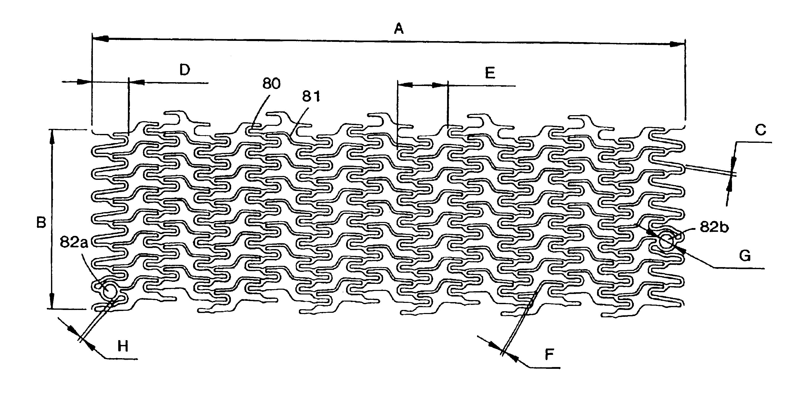
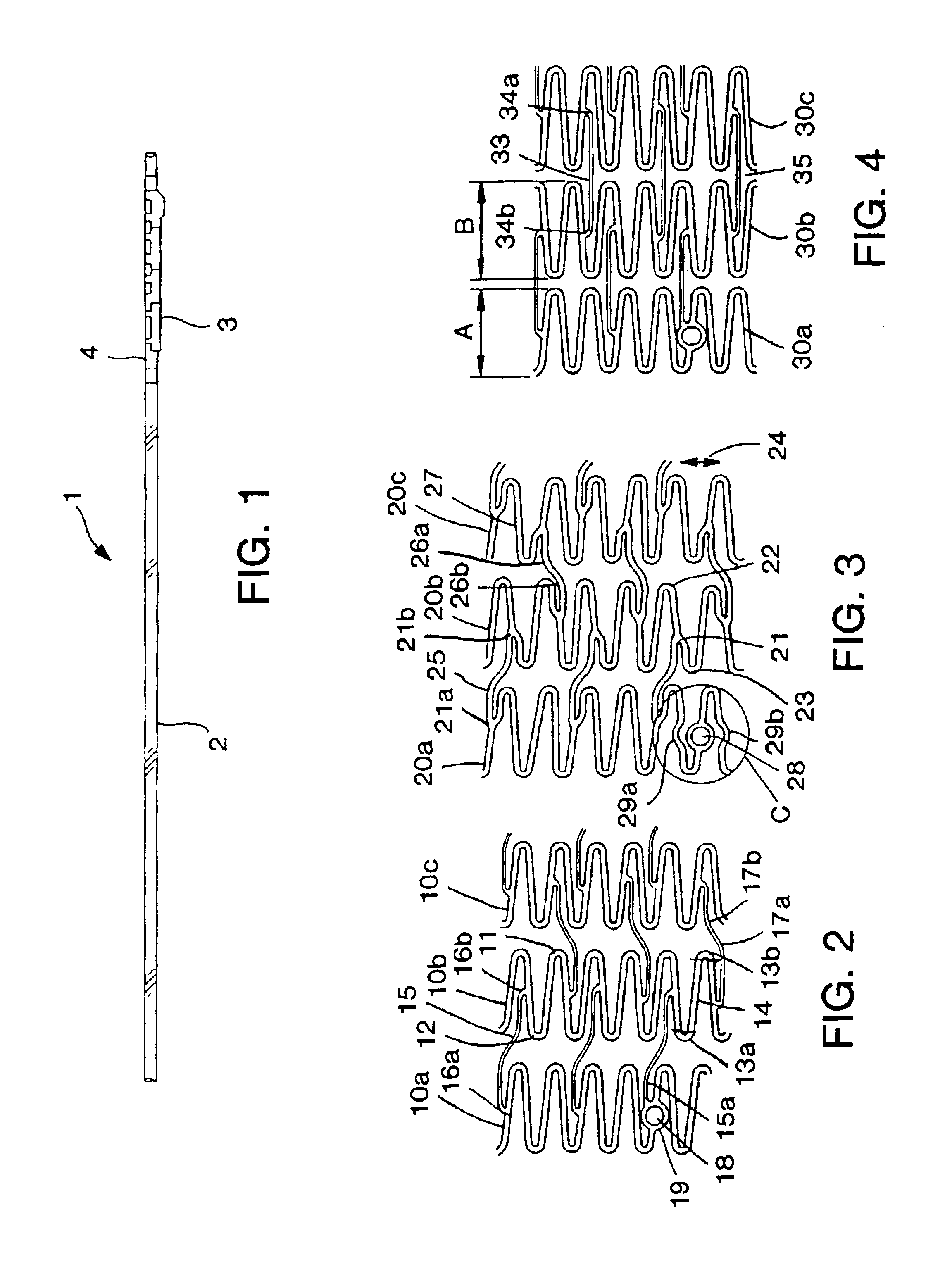
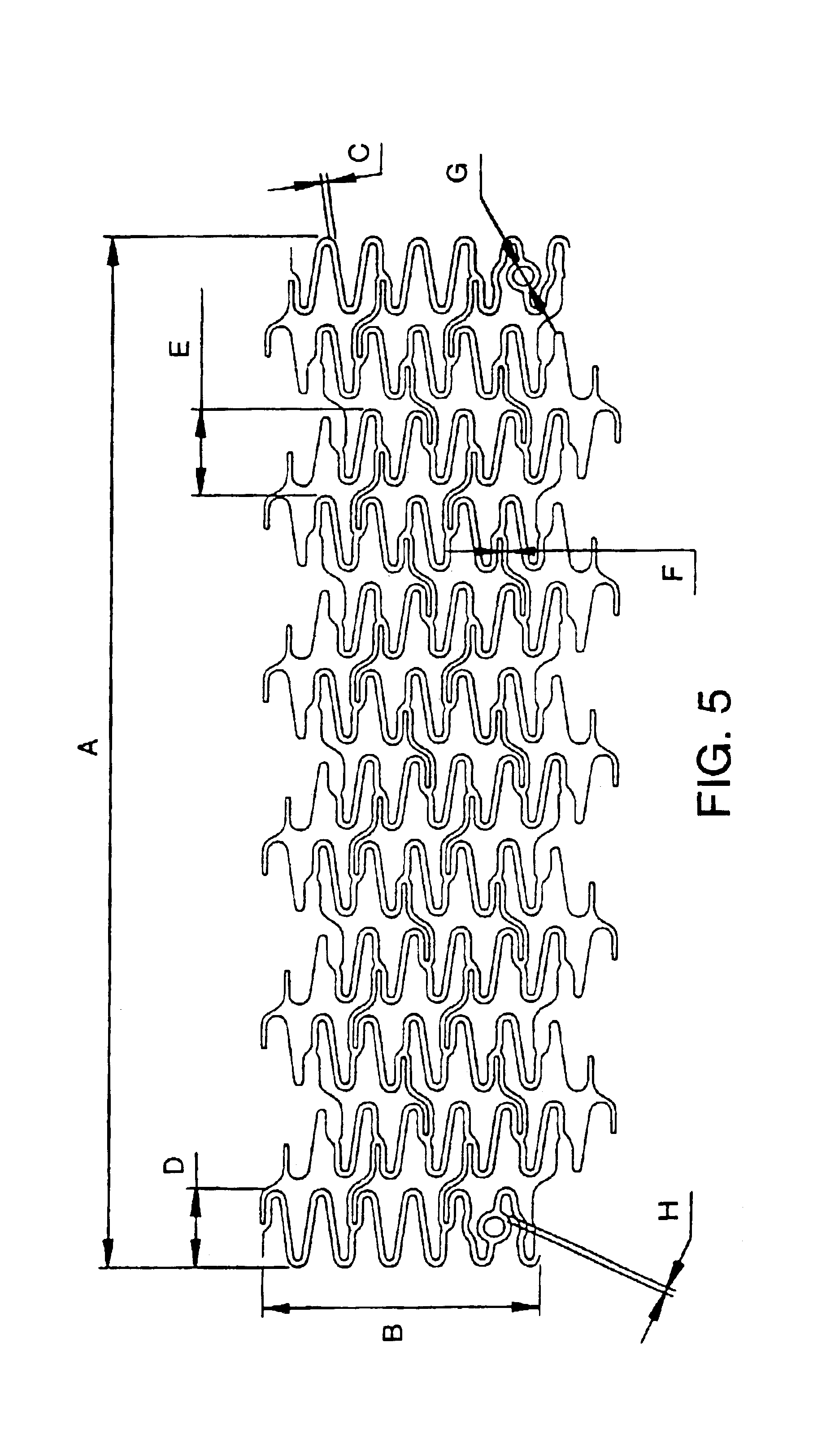
[0019]Referring now to FIG. 1, the medical device 1 of the present invention includes a catheter 2 and a stent 3 mounted on the catheter 2 in an unexpanded condition. The stent 3 has a hollow, cylindrical body made with a plurality of rings. As shown, the stent 3 is crimped over a balloon 4 affixed to the catheter 2 near the distal end of the catheter 2. The stent 3 can include a variety of configurations as shown in FIGS. 2 to 14 which are shown in an open and flattened configuration as they would appear in an unexpanded and uncrimped condition. The balloon 4 can be practically any balloon suitable for angioplasty procedures and capable of inflation to 8 atmospheres of pressure. A preferred type of balloon 4 is a balloon with multiple folds which permits the stent to expand evenly that is approximately the same length as the stent. In addition to crimping, the stent 3 can be held onto the balloon 4 by retention techniques that are well known to those skilled in the art.

[0020]Referr...


PUM


Abstract

A medical device includes a catheter and a stent mounted on the catheter, the stent having a hollow, cylindrical body made with a plurality of rings. The rings each extend circumferentially around the cylindrical body and include an undulating series of peaks and valleys. The rings are joined together by a series of links which are shaped and arranged to promote longitudinal flexibility as the stent is delivered on the catheter and effective scaffolding after deployment. In one aspect of the invention, the rings are provided with inflection points on some portions of the rings which extend in a generally circumferential direction for a short distance. A link is joined at one end at the inflection point on one ring and also joined at a second end at a second inflection point on an adjacent ring. This construction allows the crimped stent to flex longitudinally when it is subjected to bending forces such as those encountered during delivery of the stent and catheter through a tortuous coronary artery.

Description

[0001]This application is a divisional of prior U.S. patent application Ser. No. 09 / 292,991, filed Apr. 16, 1999 now U.S. Pat. No. 6,730,116.BACKGROUND OF THE INVENTION[0002]This invention relates to intraluminal endovascular stenting, a method by which a prosthesis is inserted into a body tube and expanded so as to reopen a collapsed vessel wall and prevent the wall from recollapsing into the lumen. Endovascular stenting is particularly useful for arteries which are blocked or narrowed and is an alternative to surgical procedures that intend to bypass the occlusion.[0003]Percutaneous transluminal coronary angioplasty (PTCA) is used to open coronary arteries which have been occluded by a build-up of cholesterol fats or atherosclerotic plaque. Typically a guidewire is steered through the vascular system to the site of therapy. A guiding catheter, for example, can then be advanced over the guidewire and a balloon catheter advanced within the guiding catheter over the guidewire. The ba...

Claims


Application Information

Patent Timeline
Patent Type & Authority Patents(United States)
IPC IPC(8): A61F2/06A61F2/00A61F2/84A61F2/90
CPCA61F2/91A61F2/915A61F2002/91525A61F2002/91533A61F2002/91583A61F2250/0098A61F2230/0054
Inventor WOLINSKY, LONELOSHAKOVE, AMIR DAVIDPENNER, ARVINATIV, OFFERNAOR, GILDUFFY, NIALL
Owner MEDTRONIC INC
Learn More