Endpoint detection for high density plasma (HDP) processes

a plasma chamber and endpoint detection technology, applied in the field of semiconductor processing, can solve problems such as inconsistent or misleading emission signals, serious problems, and defects that are likely to negatively affect the entire chip, and achieve optimal plasma etching or cleaning, avoid over-cleaning/etching and under-cleaning/etching, and save cleaning tim

Inactive Publication Date: 2005-07-19
NOVELLUS SYSTEMS +1
View PDF67 Cites 33 Cited by
  • Summary
  • Abstract
  • Description
  • Claims
  • Application Information

AI Technical Summary

Benefits of technology

[0017]Advantageously, the present invention allows for optimal plasma etching or cleaning of a plasma chamber by providing a real-time, in-situ endpoint detection method and system which avoids over-cleaning / etching and under-cleaning / etching. Accumulated by-products are cleaned from a plasma chamber without wasting cleaning time or expensive plasma cleaning gas while also avoiding chamber wall corrosion.

Problems solved by technology

Reaction by-products can deposit on the inside surface of the chamber walls and cause serious problems as they accumulate.
For example, in addition to affecting the chamber processing conditions, thereby degrading the processing stability, the accumulated by-products on the chamber walls may dislodge and settle on the surface of the substrate causing defects that are likely to negatively affect the entire chip.
A major problem with OES monitoring encountered during a plasma clean or etch process is inconsistent or misleading emission signals due to several reasons.
One cause may be the build up of contaminants on the surface of the detection window itself.
This problem results in false readings of the state of the etch process and inefficient cleaning.
Further, contaminants on the window may be getting etched by the plasma to give inconsistent readings.
Thus, it is obvious that either under-cleaning or over-cleaning is likely to occur.
Under-cleaning may lead to particle problems and degradation of processing stability.
Over-cleaning results in the highly reactive cleaning gases attacking the chamber wall and shortening its lifetime.
Further, expensive cleaning gases may be wasted and cleaning time is not optimized.

Method used


Image

  • Endpoint detection for high density plasma (HDP) processes
  • Endpoint detection for high density plasma (HDP) processes
  • Endpoint detection for high density plasma (HDP) processes

Examples


Embodiment Construction

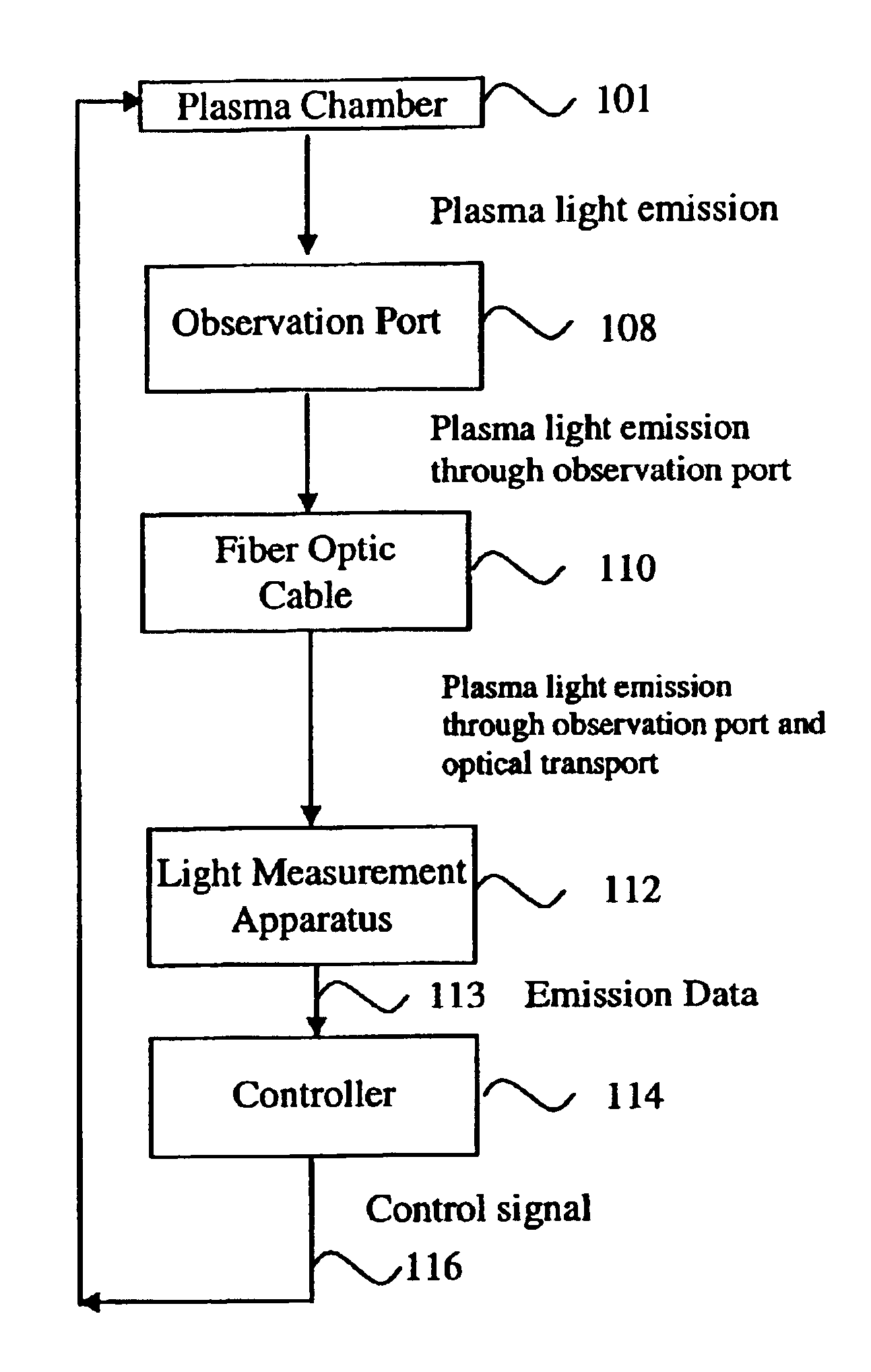
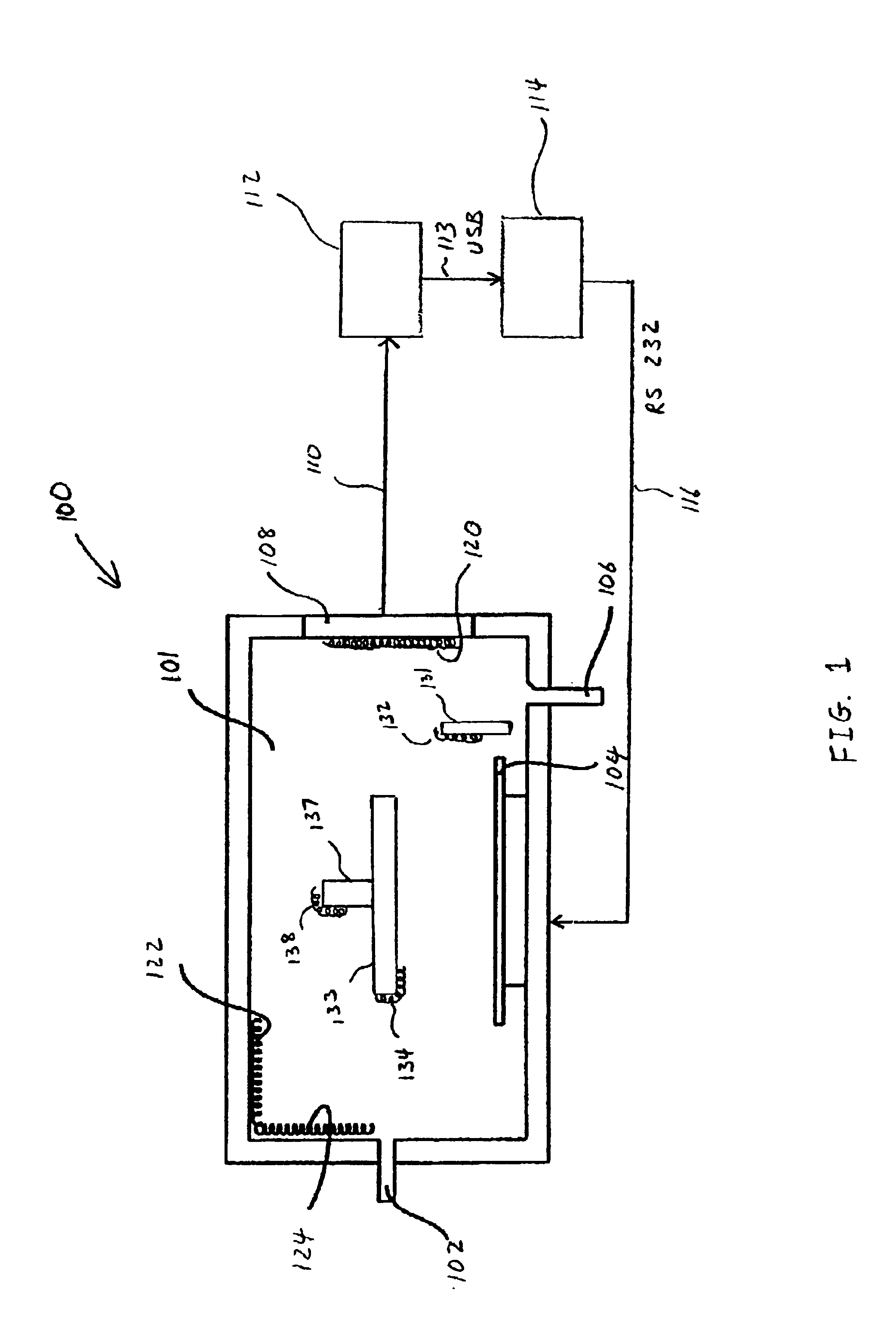
[0024]FIG. 1 illustrates a system 100 for monitoring and detecting the endpoint of a plasma clean or etch process in accordance with one embodiment of the present invention. A cross section of one example of a plasma chamber 101 is shown, including a plasma source gas outlet 102, a gas inlet 106, a wafer holder 104, an observation port 108, and a electrode / shower head 133.

[0025]Observation port 108 is provided in the main body of plasma chamber 101 and may be made of corrosion resistant material that allows light to pass through, such as quartz glass or sapphire. Observation port 108 may include a window and / or a light pipe in one example. Accordingly, optical emissions that are radiated from the inside of chamber 101 can be detected and measured through observation port 108.

[0026]One example of a plasma chamber 101, with no intent to limit the invention thereby, is a SPEED™ plasma chamber, available from Novellus Systems, Inc. of San Jose, Calif. Electrode / shower head 133 is powere...


PUM

PropertyMeasurementUnit
wavelengthaaaaaaaaaa

Abstract

A method and system are provided for endpoint detection of plasma chamber cleaning or plasma etch processes. Optical emission spectroscopy is utilized to determine a spectral emission ratio of two or more light emitting reaction components at wavelengths in close proximity. When a spectral emission ratio or derivative thereof or mathematical function thereof falls below a selected threshold value, the plasma process may be terminated within a calculated time from the threshold value prior to an endpoint value cutoff. Advantageously, the system and methods of the present invention provide real-time, in-situ monitoring of plasma clean or etch processes to optimize the process and avoid under-cleaning or over-cleaning.

Description

BACKGROUND[0001]1. Field of Invention[0002]The present invention generally relates to semiconductor processing and, more particularly, to a method and system for endpoint detection of plasma chamber cleaning processes and / or etch processes.[0003]2. Related Art[0004]Plasma etching and deposition is now a common process in semiconductor manufacturing to form active areas, lines, holes, and other device features. During plasma etching and / or deposition, process gases are introduced into a plasma chamber where they are excited by power sources to form a plasma. The plasma species react with exposed substrate areas and form volatile species which depart from the substrate, thereby forming desired features of a semiconductor device. The plasma then becomes a complex mixture of native reactant gases and etched products, including molecules, ions, neutral radicals, and other species.[0005]Plasma processing of wafers within a plasma chamber has an effect on the interior of the processing cha...

Claims


Application Information

Patent Timeline
Patent Type & Authority Patents(United States)
IPC IPC(8): H01L21/302H01L21/02C23C16/52H01J37/32
CPCC23C16/52H01J37/32935H01J37/32963
Inventor RULKENS, RONFLORIN, DIDIER
Owner NOVELLUS SYSTEMS
Why Eureka
Try Eureka