Switching power supply unit

a power supply unit and power supply circuit technology, applied in the direction of power conversion systems, dc-dc conversion, instruments, etc., can solve the problems of complex circuitry, reduced efficiency, increased size, etc., and achieve the effect of compactness and simple configuration

Inactive Publication Date: 2005-07-19
ROHM CO LTD
View PDF9 Cites 34 Cited by
  • Summary
  • Abstract
  • Description
  • Claims
  • Application Information

AI Technical Summary

Benefits of technology

[0010]Under the circumstances, an object of the invention is to provide a switching power supply unit for generating one or plural DC output voltages having different values by switching a DC input voltage, in which a coil having an ...

Problems solved by technology

However, the power supply circuits are complicated in circuitry because a multistage charge pump circuit is provided to obtain one output voltage.
Loss in the charge pump circuit reduces efficiency, and the circuit requires an extra space which results in an increased size.
Since the switching power supply units according to the related art are low in conversion efficiency and are...

Method used


Image

  • Switching power supply unit
  • Switching power supply unit
  • Switching power supply unit

Examples


first embodiment

(First Embodiment)

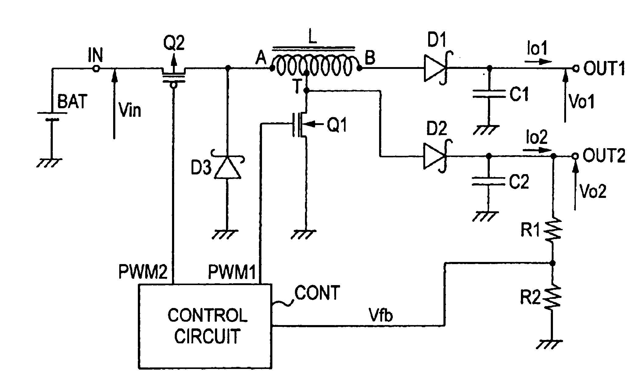
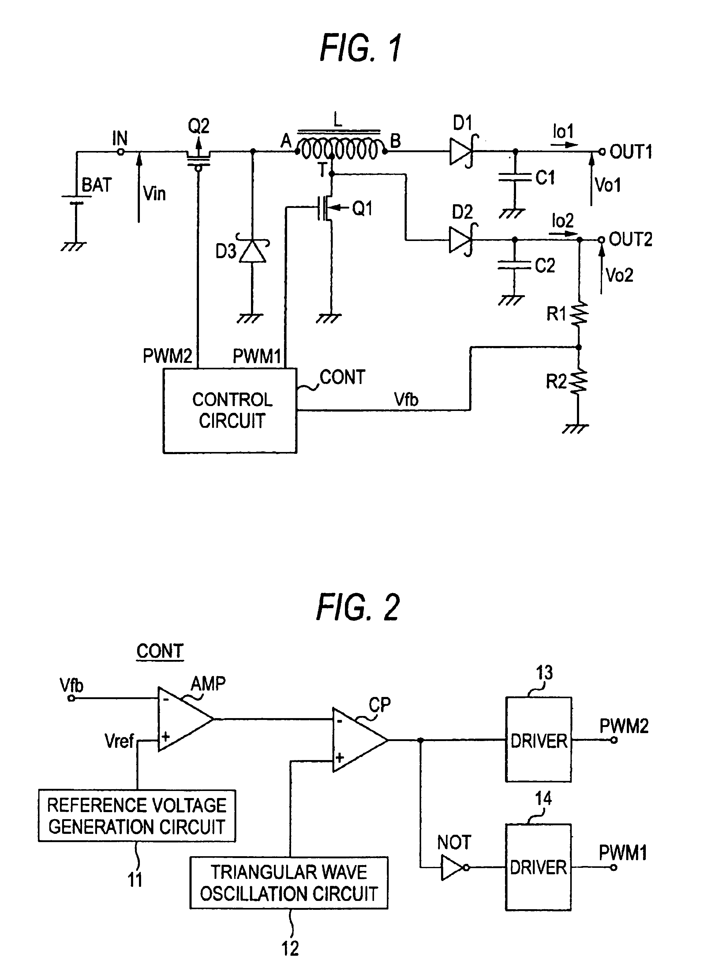
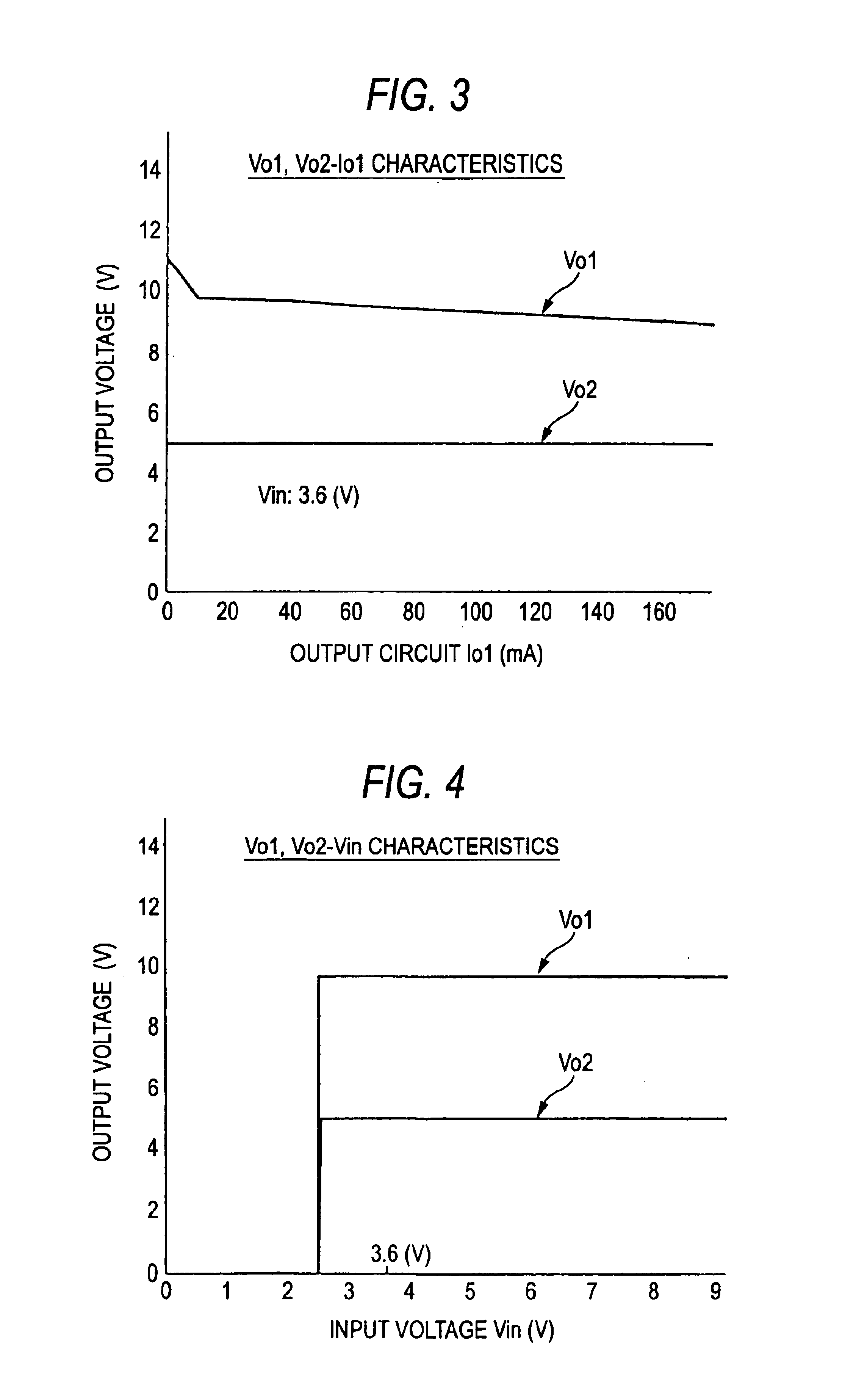
[0040]FIG. 1 illustrates a configuration of a switching power supply unit according to a first embodiment of the invention, and FIG. 2 illustrates an internal configuration of a control circuit in the same. FIG. 3 shows output voltage versus output current characteristics, and FIG. 4 shows output voltage versus input voltage characteristics. Basically, the switching power supply unit shown in FIG. 1 steps up a DC input voltage Vin to obtain DC output voltages Vo1, Vo2. As the DC output voltages may be obtained by decreasing the input voltage Vin through setting of conditions, no limitation is therefore placed on the voltage values.

[0041]In FIG. 1, a positive side of a battery BAT is connected to an input terminal IN, and a negative side of the battery BAT is connected to a ground as a common potential point. The DC input voltage Vin is thus applied to the input terminal IN.

[0042]A coil L, which winding is wound around a magnetic core, has a first terminal A, a seco...

second embodiment

(Second Embodiment)

[0077]FIG. 5 illustrates a configuration of a switching power supply unit according to a second embodiment of the invention. In the second embodiment, the first switch Q1 turning on and off under control of the switching signal PWM1 is connected between the second terminal B of the coil L having an intermediate tap and the ground. The other configuration is similar to that in FIG. 1, and two output voltages Vo1 and Vo2 independent of the input voltage Vin are obtained.

[0078]Also in the switching power supply unit in FIG. 5, (i) load regulation is at a practical level; (ii) efficiency is as high as about 77%; and (iii) neither first output voltage Vo1 nor second output voltage Vo2 has input voltage dependence.

third embodiment

(Third Embodiment)

[0079]FIG. 6 illustrates a configuration of a switching power supply unit according to a third embodiment of the invention. The third embodiment is different from FIG. 1 in that the gate of the first switch Q1 is connected to the first terminal A of the coil L having an intermediate tap. Since the potential at the first terminal A equals an input voltage Vin when the second switch Q2 turns on and approximately equals the ground potential when the second switch Q2 is turned off, the first switch Q1 turns on and off substantially simultaneously with the second switch Q2. Therefore, the switching power supply unit of the third embodiment operates similarly to the first switching power supply unit in FIG. 1.

[0080]In the switching power supply unit in FIG. 6, since the gate of the first switch Q1 is connected to the first terminal A and is therefore connected to the ground through the diode 3, the control circuit CONT outputs only one switching signal PWM1. Thus, it is ...


PUM


Abstract

Accumulation and emission of energy in and from a coil having an intermediate tap is controlled by switching a DC input voltage from a DC power source on and off. Controlled voltages generated at a plurality of terminals are rectified and smoothed to output a plurality of DC output voltages. Connection to a reference voltage is controlled such that the voltages generated at the plurality of terminals are not dependent on the DC input voltage during the on-off switching. Therefore, a switching power supply unit is provided in which a coil having an intermediate tap is used to allow a simple configuration, to convert a DC input voltage into a plurality of DC output voltages with high efficiency, and to achieve compactness.

Description

BACKGROUND OF THE INVENTION[0001]1. Field of the Invention[0002]The present invention relates to a switching power supply unit that switches an input voltage to generate one or plural output voltages having different values.[0003]2. Description of the Related Art[0004]Portable telephones, digital cameras, PDAs, and personal computers require a plurality of DC voltages having different voltage values as power supply voltages for LCDs (liquid crystal displays) and CCDs (charge-coupled devices).[0005]A transformer is normally used in a power supply unit for obtaining a plurality of DC voltages. A DC power supply unit has a configuration in which a DC input voltage applied to a primary winding of such a transformer is switched by a PWM control signal and a voltage induced at a secondary winding is rectified and smoothed to output a plurality of DC output voltages.[0006]The power supply unit utilizing a transformer has low converting efficiency (e.g., about 50 to 70%) as a power supply u...

Claims


Application Information

Patent Timeline
IPC IPC(8): H02M3/158H02M3/04H02M3/155
CPCH02M3/158H02M2001/009H02M1/009H02M3/155
Inventor HOSHINO, TAICHIOYAMA, EITARO
Owner ROHM CO LTD
Why Eureka
Try Eureka