Apparatus and method for a digital delay locked loop

Inactive Publication Date: 2005-07-19
RAMBUS INC
View PDF21 Cites 15 Cited by
  • Summary
  • Abstract
  • Description
  • Claims
  • Application Information

AI Technical Summary

Benefits of technology

[0006]In accordance with a first aspect of the present invention, a circuit for selectively delaying a reference clock signal is provided. The circuit includes a phase splitter coupled to a first delay line and a second delay line. Each delay line includes a set of output taps and has a multiplexor that is selectively coupled to the output taps.

Problems solved by technology

However, high speed clock signals often becom

Method used


Image

  • Apparatus and method for a digital delay locked loop
  • Apparatus and method for a digital delay locked loop
  • Apparatus and method for a digital delay locked loop

Examples


Embodiment Construction

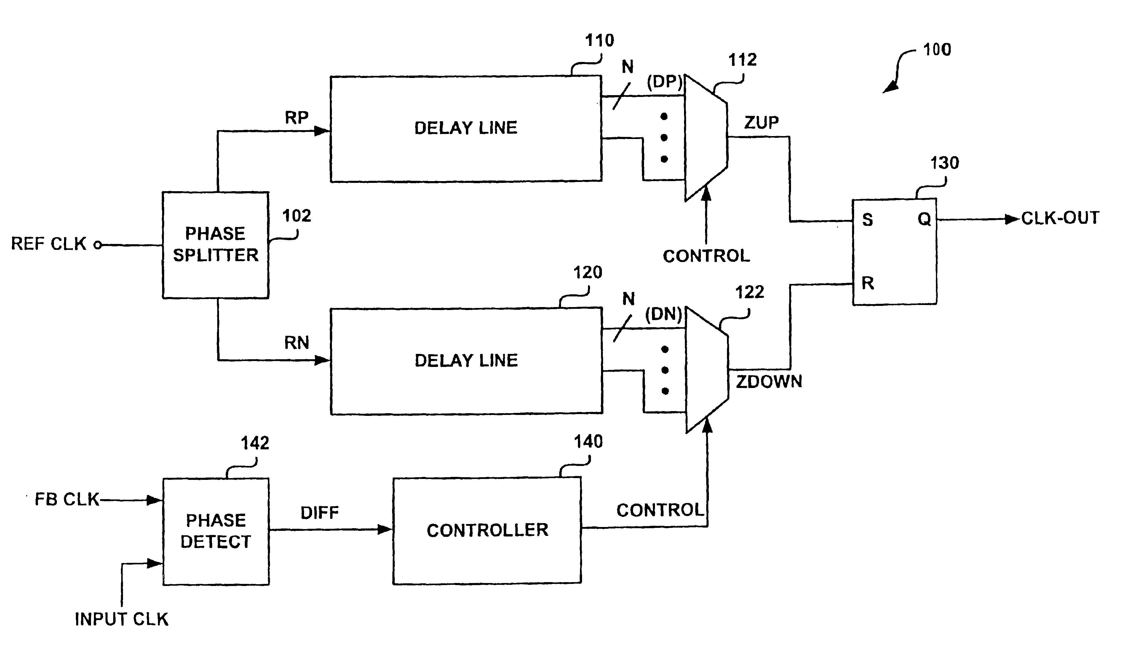
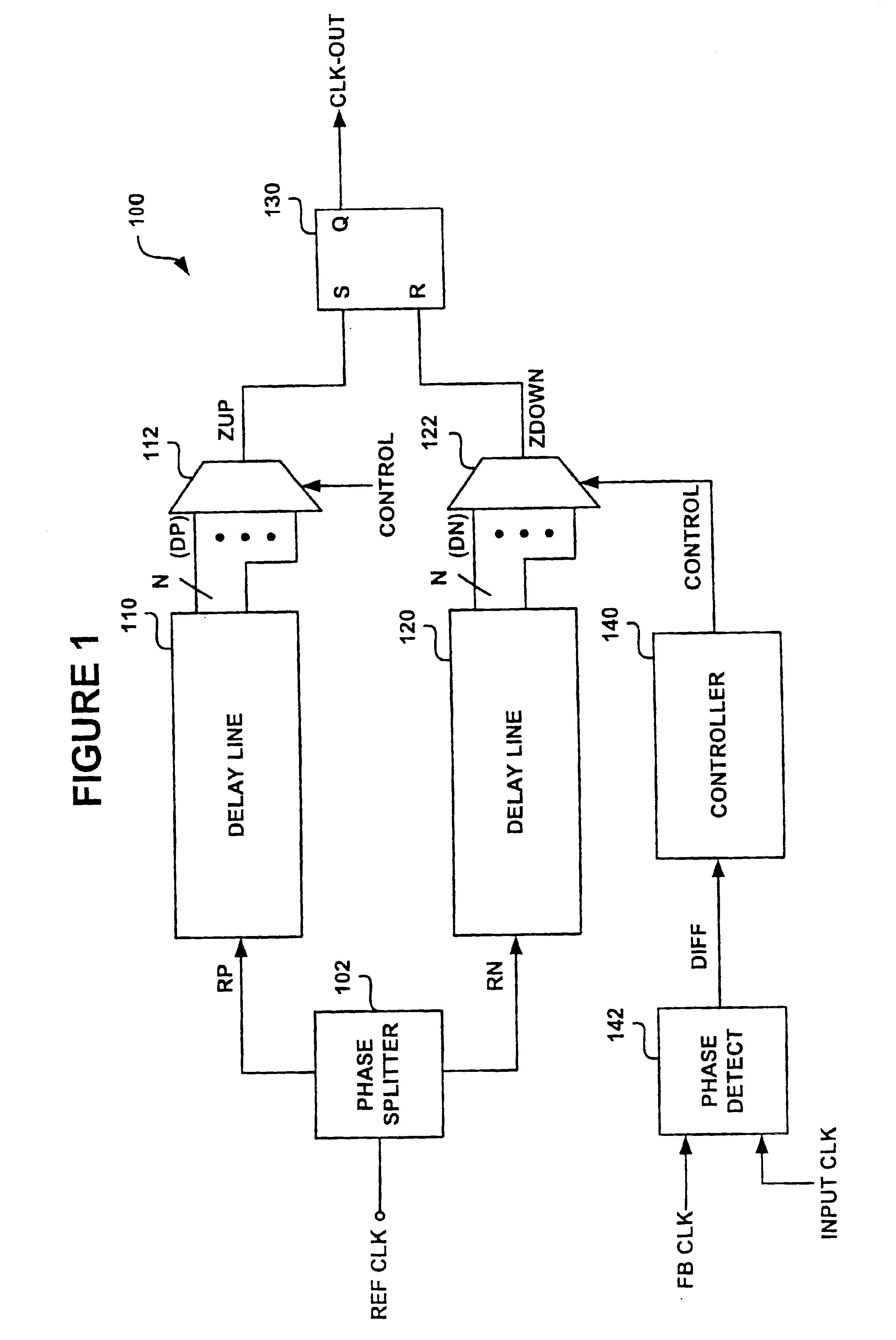
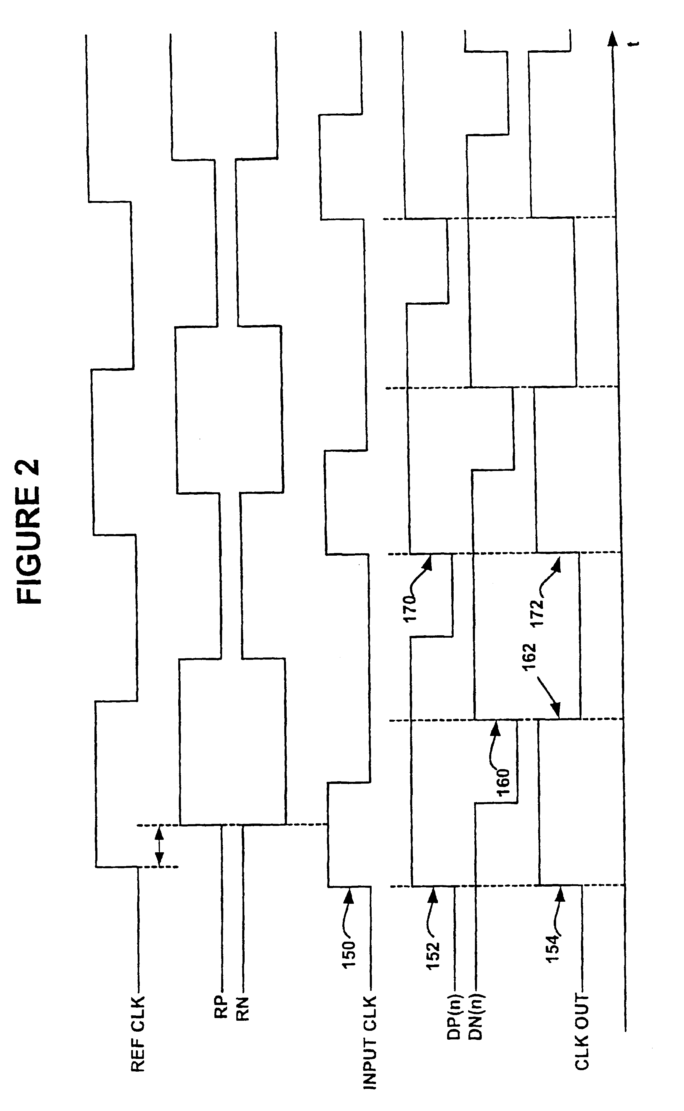
[0027]In one preferred embodiment, a reference clock having a correct duty cycle, e.g. 50%, is split into an in-phase clock reference signal and a complementary reference clock signal, each of which is successively delayed using a pair of delay lines. A set of output taps on the delay line allows the selection of and variation in the length of the delay. A pair of multiplexors (MUXes) is used to select one output tap from each of the delay lines. In accordance with one preferred embodiment, a rising edge of a signal from the output tap selected from the delay line used to delay the in-phase reference signal is used to produce a rising edge in an output clock signal. Then, a rising edge of a signal from the output tap selected from the delay line used to delay the complementary reference signal is used to produce a falling edge in the output clock signal. A feedback clock signal is compared to the input clock signal in order to obtain a difference signal that reflects the phase relat...


PUM


Abstract

A circuit and method is shown for digital control of delay lines in a delay locked loop (DLL) system. A pair of multiplexors (MUXes) is used to select output taps from a pair of complementary delay lines that delay a reference clock signal in order to lock onto a received clock signal. An output tap from one delay line is used to produce a rising edge in an output clock signal while a corresponding tap in the complementary delay line is used to produce a falling edge in the output signal in order to correct for distortion. The MUXes are controlled based on a phase difference detected between the received clock signal and a feedback clock corresponding to the output clock signal. Another aspect of the present invention provides for generation of a quadrature clock by interpolating between the rising and falling edges selected for the output clock signal. Still another aspect of the present invention provides for selectively disabling unused elements of the delay lines to reduce power consumption.

Description

CROSS REFERENCE TO RELATED APPLICATIONS[0001]This is a continuation of U.S. patent application Ser. No. 10 / 112,963, filed on Mar. 29, 2002, now U.S. Pat. No. 6,642,760. The entire disclosure of U.S. patent application Ser. No. 10 / 112,963 is herein incorporated by reference.FIELD OF THE INVENTION[0002]This present invention relates to digital circuits. More specifically, it relates to delay locked loop design.BACKGROUND OF THE INVENTION[0003]Accurate high-speed clock signals are often used for transmitting and receiving data in high-speed circuits, such as high-speed memory devices or high speed bus channels. However, high speed clock signals often become distorted during transmission and reception. Consequently, high speed circuits, such as dynamic random access memory (DRAM) devices, often recover an externally provided high-speed clock signal by locking an accurate internally generated clock signal to the distorted externally provided clock signal.[0004]A delayed locked loop (DLL)...

Claims


Application Information

Patent Timeline
IPC IPC(8): H03K3/037H03K3/00H03L7/08H03L7/081
CPCH03K3/037H03L7/0802H03L7/0814H03K3/0375
Inventor ALON, ELADBEST, SCOTT
Owner RAMBUS INC
Why Eureka
Try Eureka