Mirror rocking member for optical deflector

Inactive Publication Date: 2005-07-19
OLYMPUS CORP
View PDF8 Cites 19 Cited by
  • Summary
  • Abstract
  • Description
  • Claims
  • Application Information

AI Technical Summary

Benefits of technology

[0010]An object of the present invention is to provide a mirror rocking member for an optical deflect

Problems solved by technology

The reduction of the thickness of the movable mirror deteriorates the rigidity of the movable mirror.
In a mirror having a siz

Method used


Image

  • Mirror rocking member for optical deflector
  • Mirror rocking member for optical deflector
  • Mirror rocking member for optical deflector

Examples


Example

[0046]First Embodiment

[0047]A first embodiment will first be described with reference to the drawings.

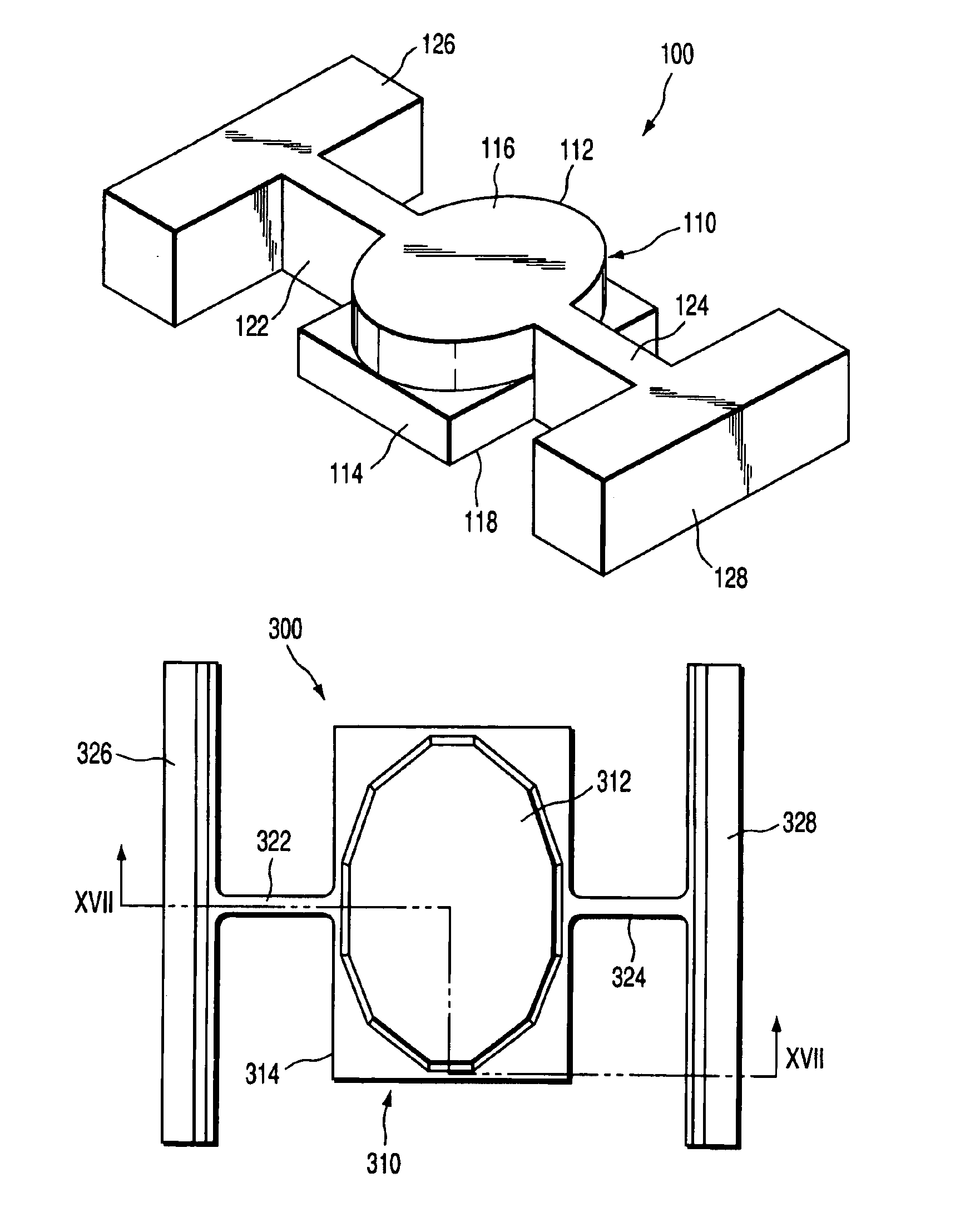
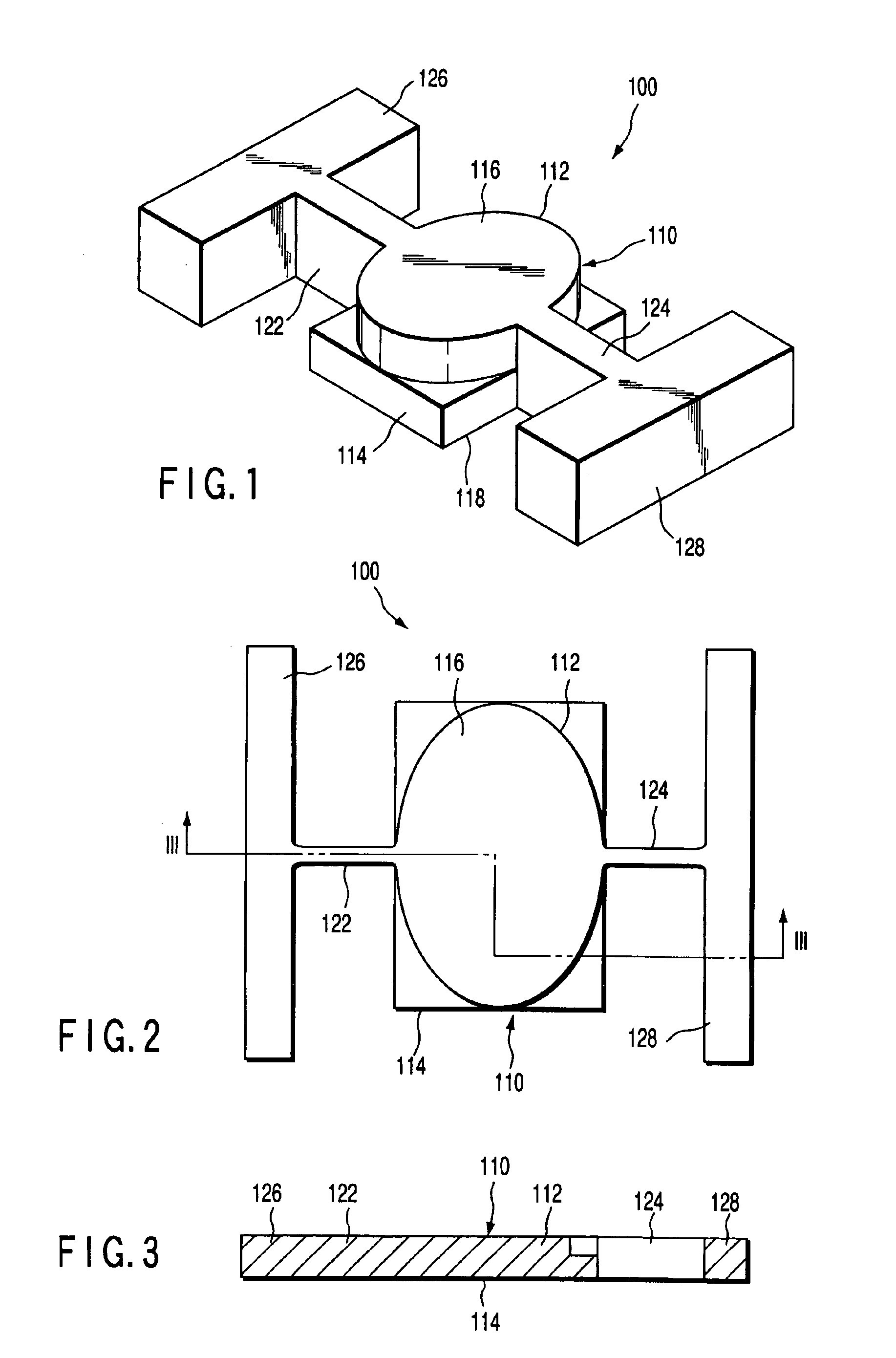
[0048]As shown in FIGS. 1 to 3, a mirror rocking member 100 comprises a movable plate 110 having a reflective surface, torsion bars 122, 124 as a pair of elastic members for rockably supporting the movable plate 110, and support members 126, 128 for supporting the torsion bars 122, 124. The torsion bars 122, 124 have rectangular sections, and symmetrically extend to opposite sides from the movable plate 110. Therefore, the movable plate 110 is rockably supported around a rocking axis passed through the torsion bars 122, 124 with respect to the support members 126, 128.

[0049]The movable plate 110 has a first portion 112 having the reflective surface, and a second portion 114 having an electric element, which constitutes a part of driving means for driving the mirror rocking member 100. The first portion 112 has a reflective-surface forming surface 116 with the reflective surface form...

Example

[0098]Second Embodiment

[0099]A second embodiment will next be described with reference to the drawings.

[0100]As shown in FIGS. 10 to 12, a mirror rocking member 200 comprises a movable plate 210 having the reflective surface, torsion bars 222, 224 as a pair of elastic members for rockably supporting the movable plate 210, and support members 226, 228 for supporting the torsion bars 222, 224. The torsion bars 222, 224 have rectangular sections, and symmetrically extend to opposite sides from the movable plate 210. Therefore, the movable plate 210 is rockably supported around the rocking axis passed through the torsion bars 222, 224 with respect to the support members 226, 228.

[0101]The movable plate 210 has a first portion 212 having the reflective surface, and a second portion 214 including an electric element constituting a part of the driving means for driving the mirror rocking member 200. As described in the first embodiment, the reflective surface may be a reflective-surface fo...

Example

[0119]Third Embodiment

[0120]A third embodiment will next be described with reference to the drawings.

[0121]As shown in FIGS. 16 and 17, a mirror rocking member 300 is a structure similar to the mirror rocking member 200 of the second embodiment, and comprises a movable plate 310 having the reflective surface, torsion bars 322, 324 as a pair of elastic members for rockably supporting the movable plate 310, and support members 326, 328 for supporting the torsion bars 322, 324. The torsion bars 322, 324 have rectangular sections, and symmetrically extend to opposite sides from the movable plate 310.

[0122]The movable plate 310 has a first portion 312 having the reflective surface, and a second portion 314 including an electric element constituting a part of the driving means for driving the mirror rocking member 300. The first portion 312 has a reflective-surface forming surface 316 with the reflective surface formed thereon, and side surfaces of the first portion 312 are inclined with ...


PUM


Abstract

There is disclosed a mirror rocking member for an optical deflector. The optical deflector comprises the mirror rocking member for deflecting light, and a driver for driving the member. The mirror rocking member comprises a movable plate having a reflective surface, an elastic member for rockably supporting the movable plate, and a support for supporting the elastic member. The movable plate has an electric element, which constitutes a part of the driver. The movable plate includes a first portion having the reflective surface, and a second portion including an electric element. The first portion has a reflective-surface forming surface with the reflective surface formed thereon, the second portion has an electric-element forming surface with the electric element formed thereon, and the reflective-surface forming surface has an area smaller than an area of the electric-element forming surface.

Description

CROSS-REFERENCE TO RELATED APPLICATIONS[0001]This application is based upon and claims the benefit of priority from the prior Japanese Patent Application No. 2000-383847, filed Dec. 18, 2000, the entire contents of which are incorporated herein by reference.BACKGROUND OF THE INVENTION[0002]1. Field of the Invention[0003]The present invention relates to a mirror rocking member for use in an optical deflector, in particular, which comprises a movable mirror having a reflective surface and rockably supported, and which rocks the movable mirror to change a direction of the reflective surface and thereby changes the direction of a light beam reflected by the reflective surface.[0004]2. Description of the Related Art[0005]A miniaturized optical deflector, which is constituted by using a micro-machining technique to integrally form a mirror, elastic member, and driving means, has been proposed. In general, for a high-speed operation of the optical deflector, a driving system with a driving...

Claims


Application Information

Patent Timeline
IPC IPC(8): G02B26/08B81B3/00B81B7/02H04N1/036H04N1/113
CPCG02B26/0841G02B26/085
Inventor MIYAJIMA, HIROSHIARIMA, MICHITSUGU
Owner OLYMPUS CORP
Why Eureka
Try Eureka