Methods and systems for low loss separation and combination of light

a technology of light separation and light combination, applied in the field of image projection, can solve the problems of prohibitively high hardware requirements for high resolution, prohibitive to display high resolution images using conventional electronic projectors, and achieve the effect of increasing the effective resolution of the projection apparatus

Inactive Publication Date: 2005-07-19
IMAX CORP
View PDF44 Cites 24 Cited by
  • Summary
  • Abstract
  • Description
  • Claims
  • Application Information

AI Technical Summary

Benefits of technology

[0011]In one embodiment, light from a projection lamp is directed into a rectangular integrating bar and is then split into two complementary half cones of light intensity distribution by the use of a total internal reflection (TIR) prism after the integrating bar. Each half cone of light is then directed by the relay optics to a SLM where it is modulated in accordance with stored image information. The SLMs may be offset or tiled with respect to each other to increase the effective resolution of the projection apparatus. After modification by the SLMs the two beams are recombined using a second TIR prism. In another embodiment, separation is accomplished by a beam splitter positioned at the pupil of a telecentric relay. Similarly, the images of the two SLMs may be combined using a second telecentric relay (with the entrance pupil at infinity) with a second beam splitter positioned at a pupil or focal plane of the second relay. The illumination distribution at the pupils is directly related to the intensity distribution at the image and object planes.
[0012]The beam splitter combining element can have surface features with both reflecting mirrored portions and transparent portions, in approximately equal proportions. The mirrored and reflecting portions may be distributed in a number of possible patterns. An additional benefit of the invention is that for recombining the modulating light some patterns, for example a checkerboard pattern, allow the combining element to act as a spatial filter and remove to some degree high frequency spatial information, which contributes to image pixellation.

Problems solved by technology

Providing high resolution images to audiences can be prohibitively expensive in terms of producing the software, and in terms of the hardware necessary to show high resolution images.
It is particularly prohibitive to display these kinds of high resolution images using conventional electronic projectors (and especially those utilizing SLMs) because it is not technically or economically feasible to produce the necessary spatial light modulators (SLM) at sufficient resolution to match the high resolution of the source material.
As well, such electronic projectors frequently fail to furnish the dynamic range and overall brightness of images provided by large-format films.

Method used


Image

  • Methods and systems for low loss separation and combination of light
  • Methods and systems for low loss separation and combination of light
  • Methods and systems for low loss separation and combination of light

Examples


Embodiment Construction

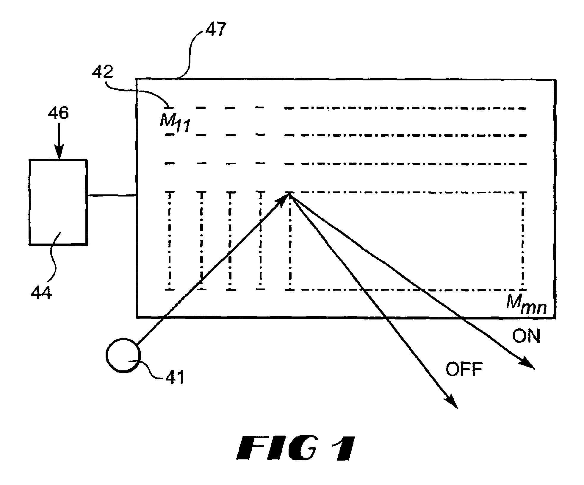
[0025]Referring first to FIG. 1, there is illustrated a spatial light modulator (SLM) 47 having an M×N array of pixels 42 arranged in rows and columns. A light beam 41 is directed at the SLM 47 and light is reflected off or transmitted by the pixels 42 in an ON direction or an OFF direction. SLM 47 could be a deformable mirror device (DMD), such as that sold by Texas Instruments, in which each of the pixels is actually a micro-steerable mirror that can be toggled between an off-state and an on-state in rapid succession, as is necessary to display an image on a projection screen. SLM 47 is connected to a driver circuit 44 that receives an electronic signal from a control circuit indicated generally as 46 and addresses each of the pixels. Alternatively, SLM 47 could be a liquid crystal array.

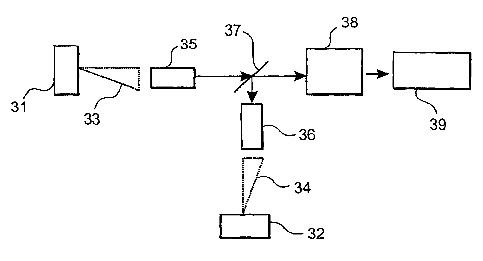
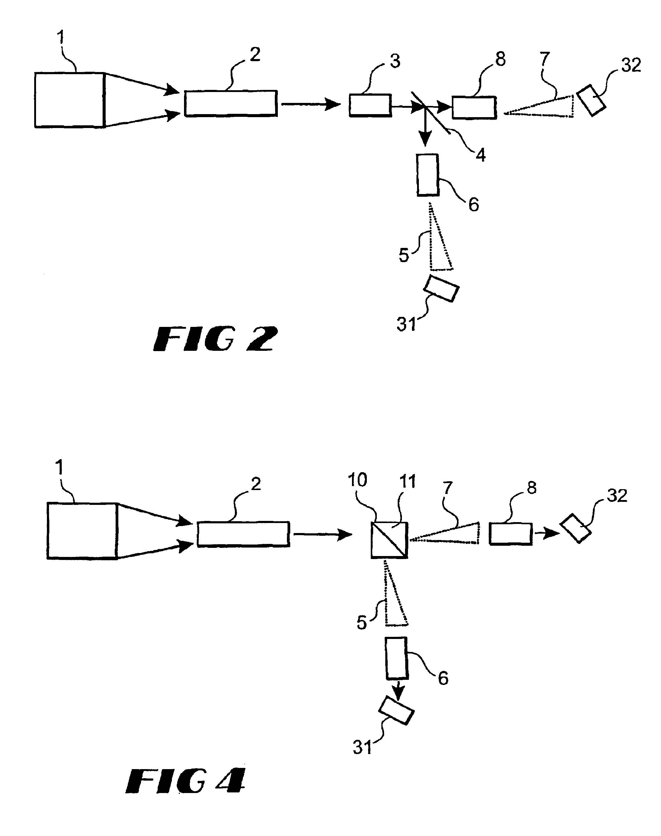
[0026]In FIG. 2, light produced by a projection lamp 1 is directed toward a rectangular integrating bar 2, which serves the purpose of providing a beam of light with a rectangular profile matching...


PUM


Abstract

A display system is disclosed that includes a light source, an integrator rod receiving a light beam from the light source and producing an integrated light beam, a beam splitting device splitting the integrated light beam into at least a first cone of light and a second cone of light, the cones of light having complementary intensity distributions, and at least a first spatial light modulator and a second spatial light modulator, wherein the first spatial light modulator is capable of selectively reflecting portions of the first cone of light in an ON direction and the second spatial light modulator is capable of selectively reflecting portions of the second cone of light in an ON direction. The display system further includes a combining device for combining the selectively reflected portions of the cones of light in the ON direction and projection optics for projecting the combined reflected cones of light.

Description

CROSS-REFERENCE TO RELATED APPLICATIONS[0001]This application claims priority to U.K. provisional application Serial No. 0009590.1, filed Apr. 18, 2000, U.S. provisional application No. 60 / 198,614 filed on Apr. 20, 2000, and International Application No. PCT / US01 / 12613 filed on Apr. 18, 2001, the entire contents of which are incorporated herein by reference.FIELD OF THE INVENTION[0002]The field of the invention is image projection in general, and electronic image projection in particular.BACKGROUND[0003]U.S. Pat. No. 5,386,253 to Fielding, incorporated herein in its entirety by this reference, discusses exemplary projection systems utilizing one or more spatial light modulators (SLMs). As noted in the Fielding patent:[0004]Spatial light modulator devices include so-called “active matrix” devices, comprising an array of light modulating elements, or “light valves,” each of which is controllable by a control signal (usually an electrical signal) to controllably reflect or transmit lig...

Claims


Application Information

Patent Timeline
Patent Type & Authority Patents(United States)
IPC IPC(8): H04N9/31G02B27/10H04N5/74
CPCG02B27/1026G02B27/126G02B27/143G02B27/144H04N5/7416H04N9/3105H04N9/3197H04N5/7458
Inventor ANIKITCHEV, SERGUEI G.READ, STEVENMOSS, GRAHAM H.
Owner IMAX CORP
Why Eureka
Try Eureka