Solid electrolytic capacitor

a solid electrolytic capacitor and capacitor technology, applied in the field of solid electrolytic capacitor structure, can solve the problems of low reliability of electrical connections and the inability to make very large capacitor elements, and achieve the effect of lowering connection reliability, small size and larger capacitan

Inactive Publication Date: 2005-07-19
TOKIN CORP
View PDF6 Cites 47 Cited by
  • Summary
  • Abstract
  • Description
  • Claims
  • Application Information

AI Technical Summary

Benefits of technology

[0011]It is an object of the present invention to provide a solid electrolytic capacitor of chip type which can attain a smaller size and a larger capacitance without lowering a connection reliability.

Problems solved by technology

The structure of the solid electrolytic capacitor of conventional surface mount type, however, has had the problem that large spaces are required for joining the capacitor element with the anode terminal and the cathode terminal, so the volume of the capacitor element cannot be made very large.
On the other hand, the recent solid electrolytic capacitor of bottom electrode structure type has had the problem that the reliability of electrical connections lowers.

Method used


Image

  • Solid electrolytic capacitor
  • Solid electrolytic capacitor
  • Solid electrolytic capacitor

Examples


first embodiment

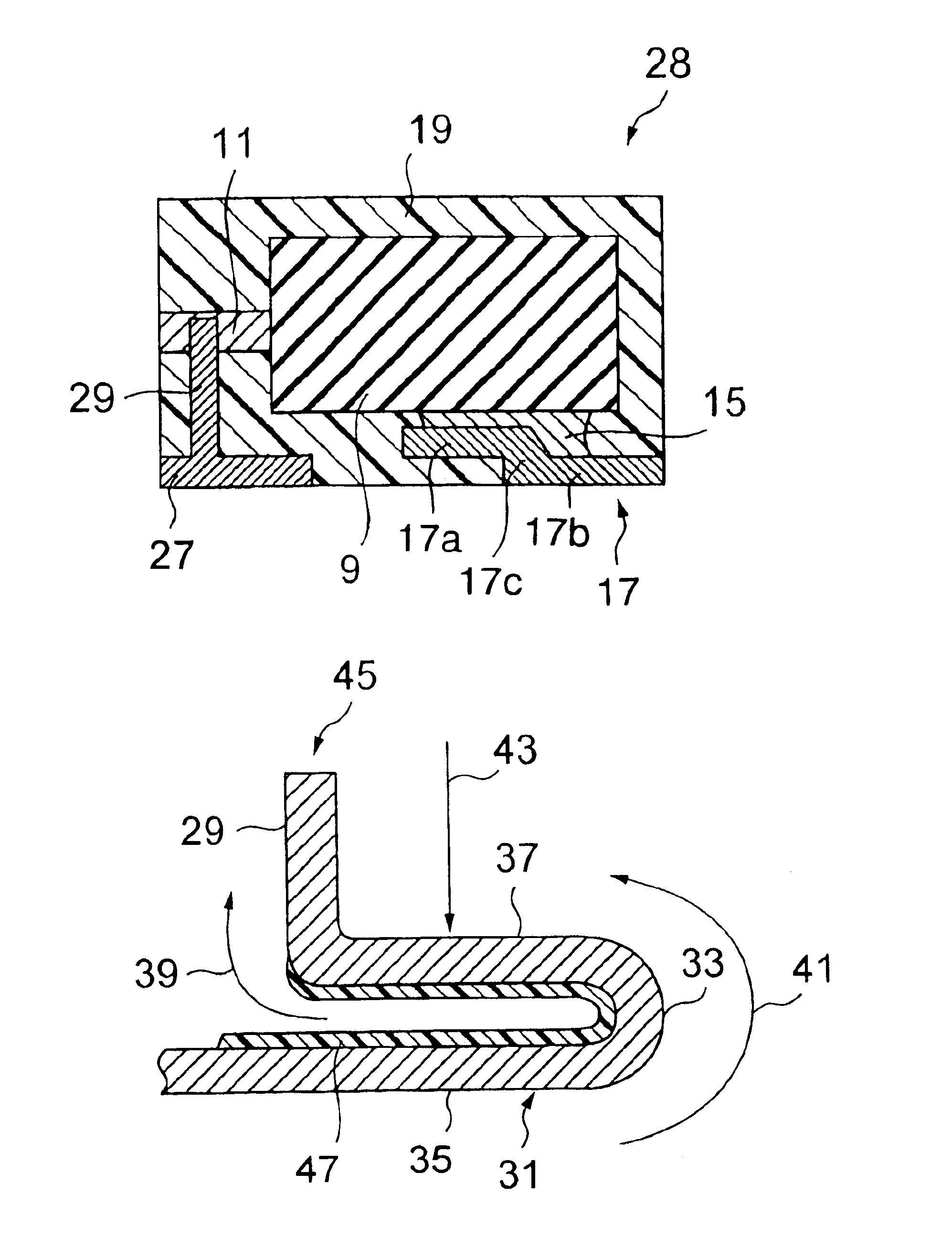
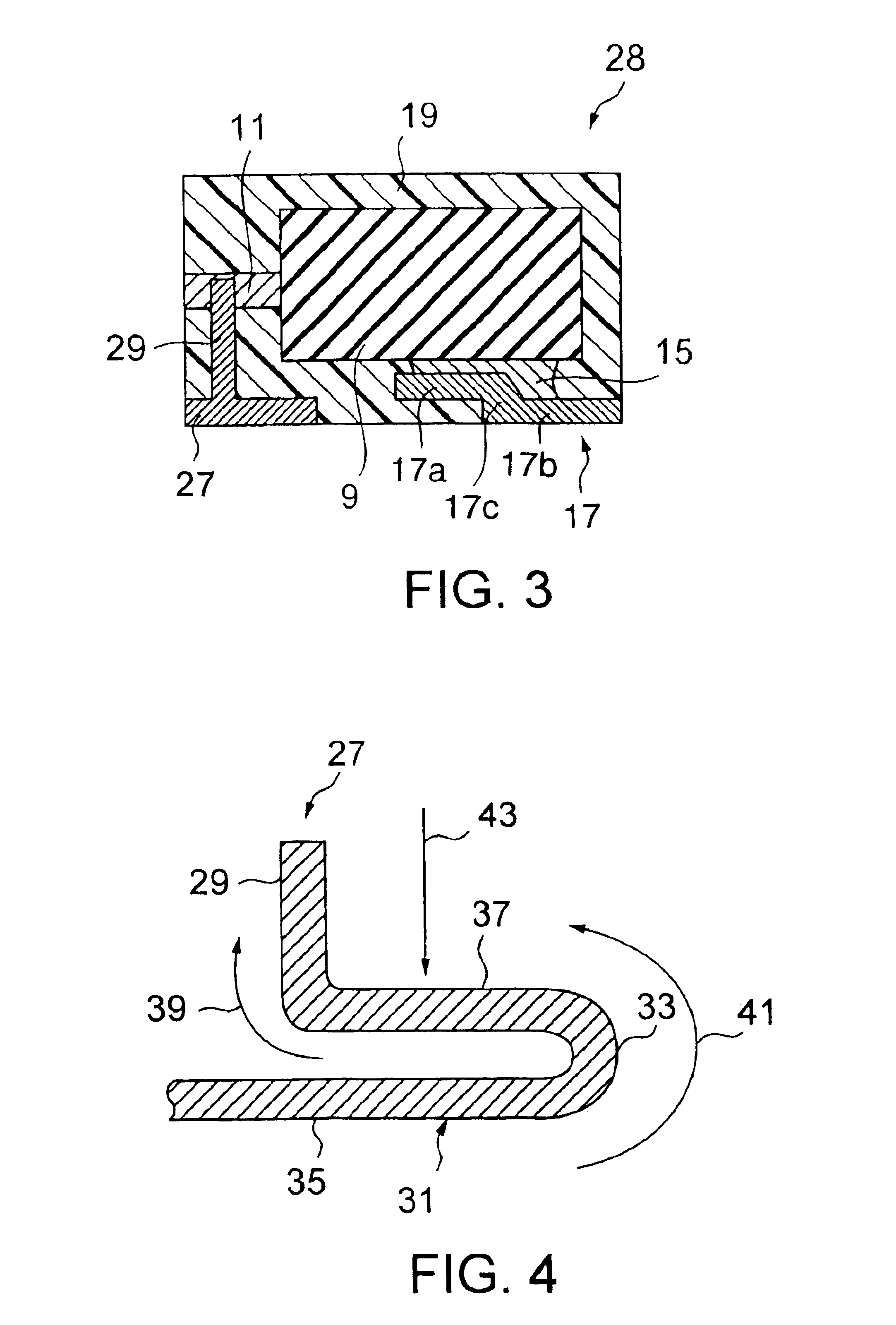
[0029]Referring to FIG. 3, in a solid electrolytic capacitor 28 according to the first embodiment of the present invention, a capacitor element 9 is connected to a cathode terminal 17 through an electroconductive adhesive 15. Besides, an anode lead 11 led out from the capacitor element 9 is connected to the end (first end) of a bent-up anode portion 29 which is the first plate piece of an anode terminal 27, by a process such as welding. Use is made as the capacitor element 9 of one having a construction similar to that of the related arts 2 and 3.

[0030]The cathode terminal 17 includes a cathode connection portion 17a being a fourth plate piece and a bottom electrode portion 17b being a fifth plate piece as form a step through an interconnection portion 17c therebetween and as are formed in parallel to each other. The upper surface of the cathode connection portion 17a is connected to a cathode portion at the outer periphery of the capacitor element 9 by the electroconductive adhesiv...

second embodiment

[0036]Referring to FIG. 5, a solid electrolytic capacitor according to the second embodiment has the same construction as that of the first embodiment except an anode terminal portion. In an anode terminal 45 according to the second embodiment of the present invention, part of a terminal surface, that is, the opposing surfaces of the mounting surface side part 35 and the communication part 37 is / are coated with a resin film 47 before the press works of this anode terminal. The resin film 47 is applied on those surfaces of the two parts 35 and 37 which are pressure-welded to each other by the crushing work, and it can enhance the sealability and joining strength of the joined surfaces. A resin to be selected for the resin film 47 may be one which is soft and ductile, which is set by heating or the like and which exhibits a high bondability. Such resins are, for example, an epoxy resin, a silicone resin and an acrylic resin, but they are not restrictive.

[0037]As described above, accor...


PUM

PropertyMeasurementUnit
bendingaaaaaaaaaa
structureaaaaaaaaaa
electroconductiveaaaaaaaaaa

Abstract

In a solid electrolytic capacitor, an anode terminal (27 in FIG. 3) has a T-shaped section in which two plate pieces intersect at right angles. One of the two plate pieces is exposed to the mounting surface of the solid electrolytic capacitor, while the other is perpendicularly erected to an anode lead (11). The two plate pieces are made of a series of continuous members.

Description

[0001]The present application claims priority to prior Japanese application JP 2002-212492, the disclosure of which is incorporated herein by reference.BACKGROUND OF THE INVENTION[0002]The present invention relates to the structure of a solid electrolytic capacitor, and more particularly to the shapes and forming methods of electrode terminals.[0003]With the miniaturization of electronic equipment, the surface mount of solid electrolytic capacitors has been necessitated, and surface-mountable solid electrolytic capacitors of chip type have been often employed.[0004]A solid electrolytic capacitor in the prior art (hereinbelow, called “related art 1”) includes a capacitor element, an anode terminal which is joined to the anode lead of the capacitor element, and a cathode terminal which is disposed at the outer periphery of the capacitor element through an electroconductive adhesive. The solid capacitor has its surroundings covered with a casing material, such as plastics material. Her...

Claims


Application Information

Patent Timeline
Patent Type & Authority Patents(United States)
IPC IPC(8): H01G9/00H01G9/04H01G9/012H01G9/008H01G4/228H01G13/00H01G9/15H01G9/042
CPCH01G9/012H01G9/15H01G9/042Y10T29/417
Inventor SANO, MITSUNORIKONO, TAKASHIYOSHIDA, KAZUTOSUZUKI, TAKASHIGE
Owner TOKIN CORP
Why Eureka
Try Eureka