Electronic apparatus including a circulation path for circulating cooling medium

a circulation path and cooling medium technology, applied in the field of electronic equipment including, can solve the problems of short cooling capacity of mpu, large noise, and difficulty in ensuring a space for accommodating a large electric, and achieve the effect of preventing a rise in temperature of the surface of the display uni

Inactive Publication Date: 2005-07-19
KK TOSHIBA
View PDF17 Cites 17 Cited by
  • Summary
  • Abstract
  • Description
  • Claims
  • Application Information

AI Technical Summary

Benefits of technology

[0017]A first object of the present invention is to provide a cooling unit and an electronic apparatus capable of preventing a rise in temperature of the surface of a display unit.
[0018]A second object of the present invention is to provide an electronic apparatus, which allows a second housing to be removed from a first housing without releasing thermal connection between a heat receiving portion and a heat generating component and which can be disassembled / reassembled easily and maintain reliability of heat conduction favorably.
[0022]The cooling medium heated through heat conduction from the heat receiving portion is cooled via the intermediate cooling means before it reaches the heat exchanging portion. Thus, the temperature of the cooling medium introduced by the heat exchanging portion can be lowered. Thus, the rise in temperature of the surface of the display unit can be suppressed despite discharging heat from the heat generating component from the display unit, so that a bad influence upon user using the electronic apparatus can be reduced to such a level having no problem.
[0027]Consequently, when removing the second housing from the first housing, it is not necessary to release thermal connection between the heat receiving portion and the heat generating component. Thus, a troublesome work of disassembling or reassembling portions corresponding to the heat generating component and heat receiving portion is not required, so that the removal of the second housing is facilitated. Further, no unreasonable force is applied to the heat generating component or the positional relationship between the heat generating component and the heat receiving portion is not changed, thereby making it possible to maintain reliability of thermal connection between the both.
[0030]In order to remove the second housing from the first housing, the first housing is opened upward so as to expose the first and second pipe lines introduced to the interior of the first housing. Next, the first and second pipe lines extending throughout the heat receiving portion and the heat exchanging portion are divided inside the first housing. Consequently, when removing the second housing having the heat exchanging portion from the first housing, the first and second pipe lines make no obstacle and the thermal connection between the heat receiving portion and the heat generating component does not have to be released. As a result, a troublesome work of disassembling / reassembling portions corresponding to the heat generating component and heat receiving portion is not required, so that the removal of the second housing is facilitated. Further, no unreasonable force is applied to the heat generating component or the positional relationship between the heat generating component and the heat receiving portion is not changed, so that reliability of thermal connection between the both can be maintained.

Problems solved by technology

If the feeding amount of cooling air is increased to aim at intensifying cooling performance of the MPU, the rotation amount of the electric fan is increased, so that there is produced such a problem that a large noise may be produced.
Additionally, because in the portable computer, a housing for incorporating the MPU and electric fan is designed so thin in a compact body, it is difficult to secure a space for accommodating a large electric fan having an excellent air feeding performance and an ideal air feeding path inside the housing.
Thus, the conventional forced air-cooling system has a fear that the cooling capacity for the MPU becomes short or reaches its limit.
As a result, if user happens to touch the surface of the display housing when opening / closing the display housing or carrying the computer, he or she may feel discomfort or heat.
However, disassembly of the periphery of such a precision MPU not only leads to damage of the MPU but also may make inappropriate the positional relationship between the heat receiving header and the MPU upon installation of the heat receiving header.
Thus, this is unfavorable in terms of maintaining reliability of thermal connection between the MPU and the heat receiving header.
If the MPU is loaded on a place difficult to access like a rear face of a circuit board, a troublesome work of disassembling the housing and taking out the circuit board is required.
This work can be said to be inappropriate in viewpoint of operation efficiency and therefore, there is a room for improvement at this point.

Method used


Image

  • Electronic apparatus including a circulation path for circulating cooling medium
  • Electronic apparatus including a circulation path for circulating cooling medium
  • Electronic apparatus including a circulation path for circulating cooling medium

Examples


first embodiment

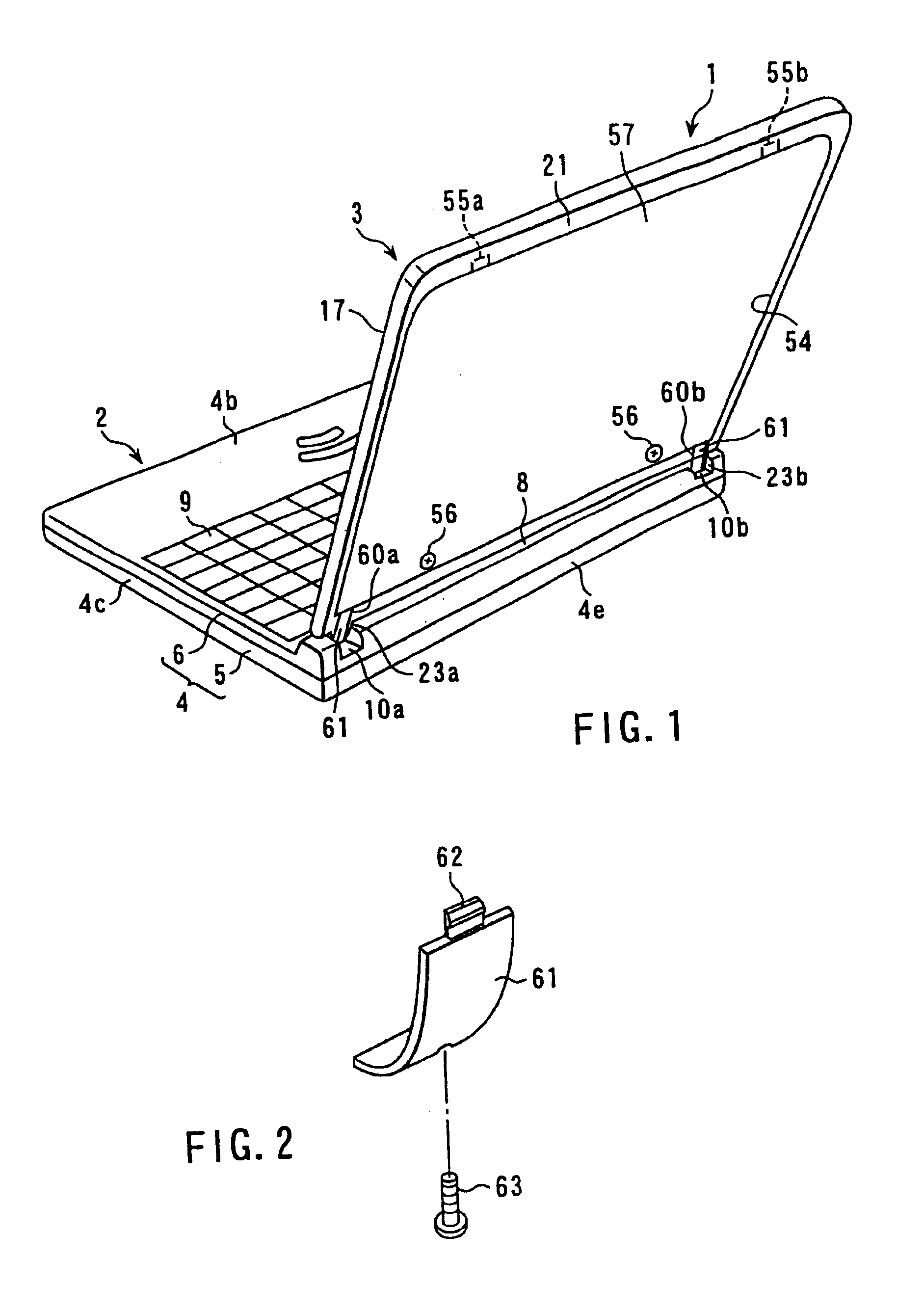
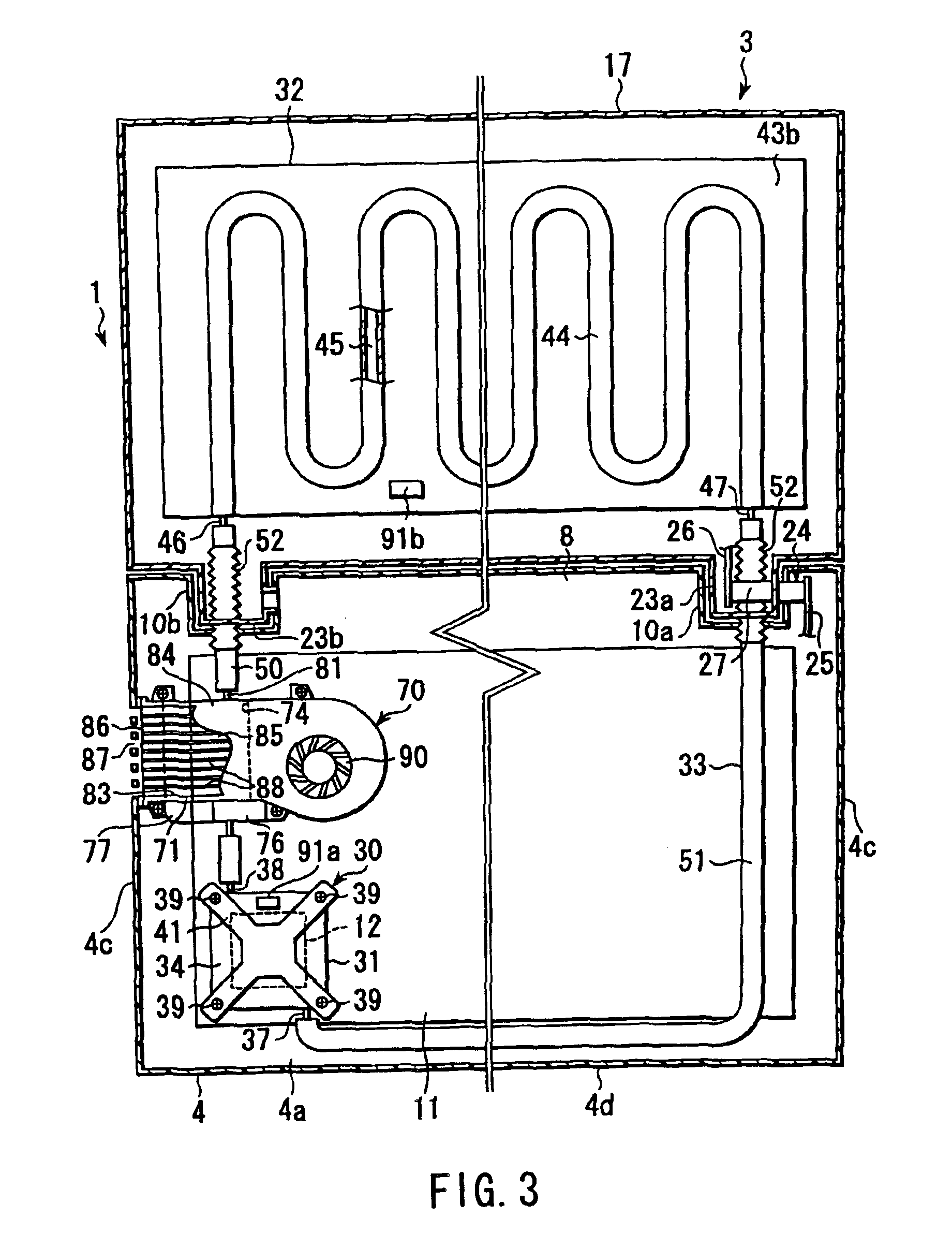
[0053]Hereinafter, the present invention applied to a portable computer will be described with reference to FIGS. 1 to 13.

[0054]FIGS. 1 and 3 show a portable computer 1 which is an electronic apparatus mentioned in this specification. The portable computer 1 comprises a computer main body 2 and a display unit 3, which is supported by this computer main body 2.

[0055]The computer main body 2 has a first housing 4 of synthetic resin. The first housing 4 is a flat box comprising a bottom wall 4a, an upper wall 4b, right / left side walls 4c, a front wall 4d and a rear wall 4e. The first housing 4 is composed of a base 5 having the bottom wall 4a and a top cover 6 having the upper wall 4b. The top cover 6 is installed detachably to the base 5. Thus, by removing the top cover 6 from the base 5, the first housing 4 is opened upward.

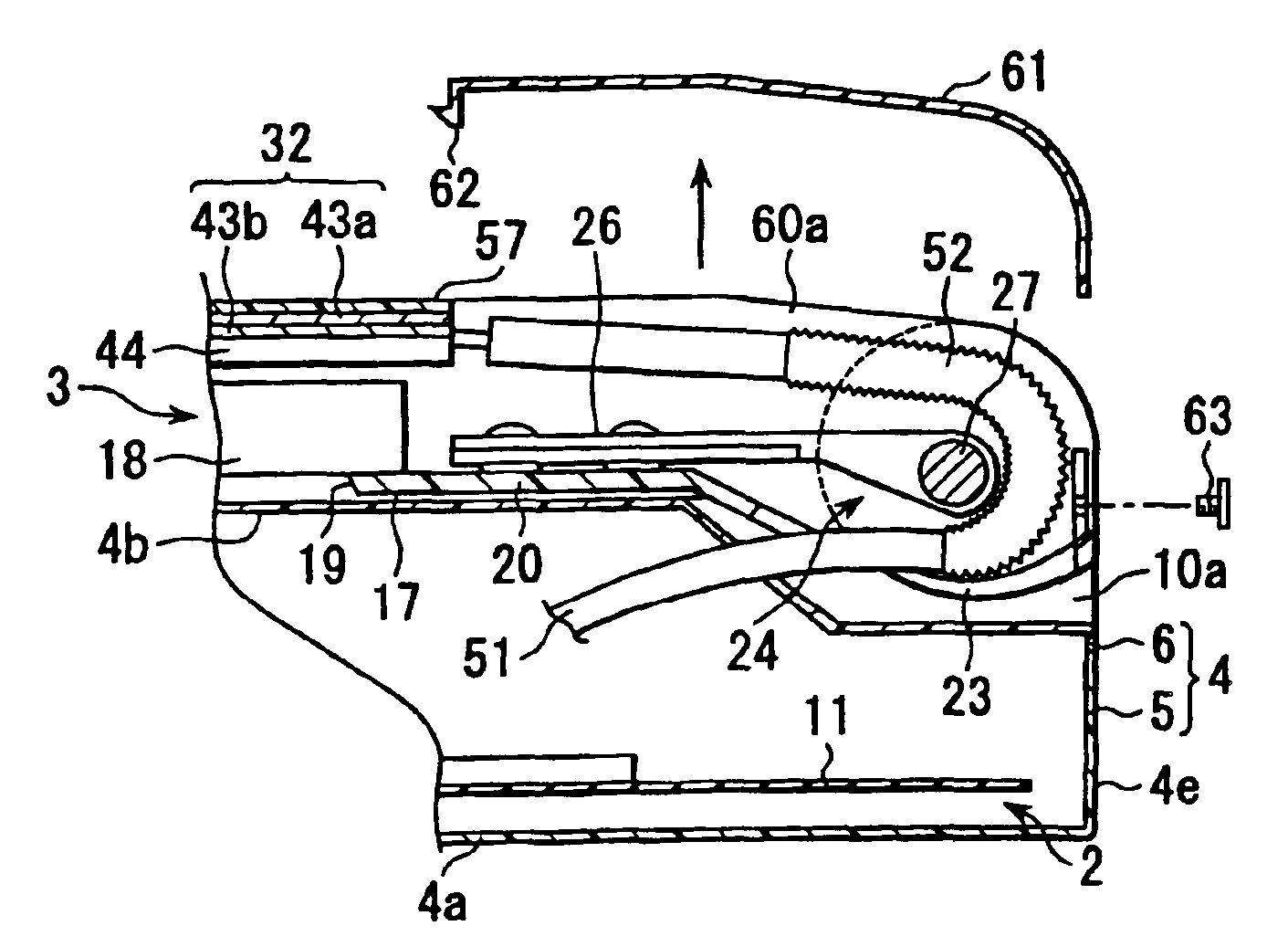
[0056]A hallow convex portion 8 protruded upward is formed at a rear end portion of the upper wall 4b of the first housing 4. The convex portion 8 is extended in ...

third embodiment

[0124]FIG. 15 shows the present invention.

[0125]This third embodiment is a further development of the second embodiment. According to the third embodiment, a connecting panel 110 for connecting the lids 61 is large enough to cover the mounting port 54 entirely. The connecting panel 110 is fit to the mounting port 54 detachably such that it is overlaid on the first heat radiating plate 43a of the heat radiator 32 supported by the display housing 17. Thus, the first heat radiating plate 43a of the heat radiator 32 is not equipped with any protective layer like shown in the first embodiment and this connecting panel 110 functions a protective layer which covers the first heat radiating plate 43a.

fourth embodiment

[0126]Further, FIGS. 16-18 show the present invention.

[0127]According to the fourth embodiment, the structure of a cooling unit 120 for cooling mainly the semiconductor package 12 is different from that of the first embodiment and other basic structure of the portable computer 1 is the same as the first embodiment. Thus, for the fourth embodiment, like reference numerals are attached to the same component as the first embodiment and a description thereof is omitted.

[0128]As shown in FIG. 16, the convex portion 8 located at the rear end portion of the first housing 4 is so constructed that both ends thereof are located inside in the width direction of the first housing 4 with respect to the side wall 4c of the first housing 4. At the rear end portion of the first housing 4 are formed a pair of display supporting portions 121a and 121b which are specified by both end faces of the convex portion 8 and a top face of the upper wall 4b.

[0129]The leg portions 23a and 23b of the display ho...


PUM


Abstract

An electronic apparatus includes a first housing including a convex portion and housing a heat generating component, a second housing including a leg portion rotatably supported by the convex portion, a heat receiving portion provided in the first housing and thermally connected to the heat generating component, a heat radiating portion provided in the second housing, and a circulation path for circulating a cooling medium between the heat receiving portion and the heat radiating portion. The circulation path extends between the first housing and the second housing through the interior of the convex portion and the interior of the leg portion. The leg portion includes an opening at the part corresponding to the circulation path for exposing the circulation path. The opening is covered with a removable lid.

Description

CROSS-REFERENCE TO RELATED APPLICATIONS[0001]This application is a divisional application of U.S. application Ser. No. 10 / 298,576, filed Nov. 19, 2002 now U.S. Pat. No. 6,728,102, which is a division of application Ser. No. 09 / 955,091, filed Sep. 19, 2001 now U.S. Pat. No. 6,510,052, all of which are incorporated herein by reference.BACKGROUND OF THE INVENTION[0002]1. Field of the Invention[0003]The present invention relates to a cooling unit for forcing a heat generating component like a semiconductor package to be cooled with liquid-like cooling medium and an electronic apparatus provided with the cooling unit, such as a portable computer.[0004]2. Description of the Related Art[0005]An electronic apparatus like a portable computer has a micro processing unit (MPU) for processing multi-media information such as characters, voices and animation. This MPU tends to increase generation of heat during its operation accompanied by currently increased processing speed and multiple functio...

Claims


Application Information

Patent Timeline
Patent Type & Authority Patents(United States)
IPC IPC(8): G06F1/20H05K7/20F28D1/03F28D15/02H01L23/473
CPCF28D1/0308G06F1/203F28D2021/0029
Inventor ISHIKAWA, KENICHIHISANO, KATSUMI
Owner KK TOSHIBA
Why Eureka
Try Eureka