Smart connect

a technology of optical interconnect and fiber connection, applied in the field of optical connectivity management, can solve the problems of increasing the density of optical interconnect at network element nodes, the inability to validate fiber connections in such systems, and the inability to change fiber connections between respective circuit cards, so as to simplify the fiber connection validation process and enhance future products

Inactive Publication Date: 2005-07-19
CIENA
View PDF6 Cites 61 Cited by
  • Summary
  • Abstract
  • Description
  • Claims
  • Application Information

AI Technical Summary

Benefits of technology

[0017]Presently, interfaces between optically connected devices are configured manually and are, therefore, prone to installation errors. Providing fiber connectivity management according to the invention will enhance future products by simplifying the fiber connection validation process and

Problems solved by technology

As seen, upgrades or re-arrangements necessarily result in the fiber connections between respective circuit cards having to be changed.
However, the optical interconnect density at network element nodes is continually increasing and is, as a result, becoming more and more complex.
According

Method used


Image

  • Smart connect
  • Smart connect
  • Smart connect

Examples


Embodiment Construction

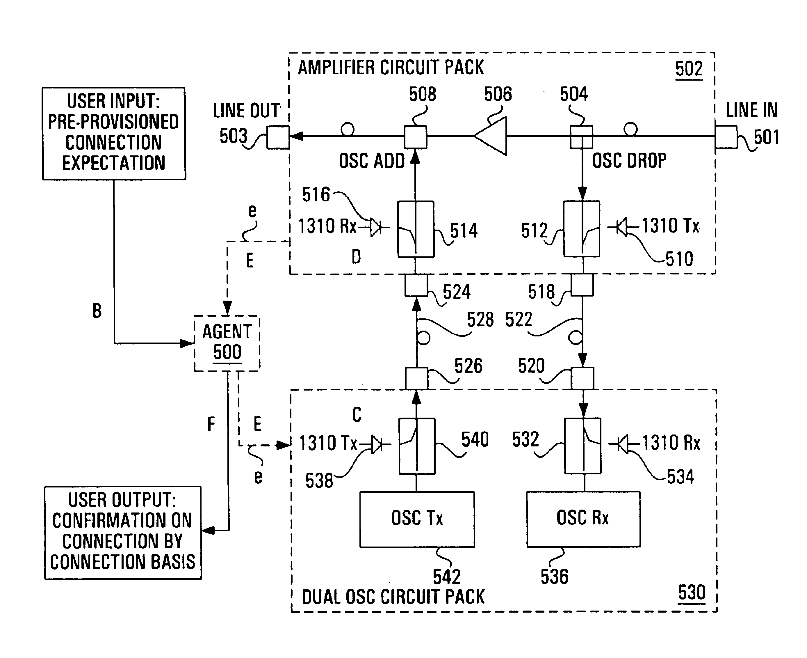
[0031]When an optical system is decomposed into multiple subsystems, the fiber connections between those subsystems are prone to installation error. An installer (or craftsperson) will generally have to manually configure the association between two respective components (or circuit packs) connected through fiber e.g. the connection between an OSC card and an amplifier card. As systems get more and more complex and the interconnect density continues to increase, trouble-shooting faulty connections becomes a daunting task for the craftsperson. The present invention seeks to simplify fiber connection management within optical networks.

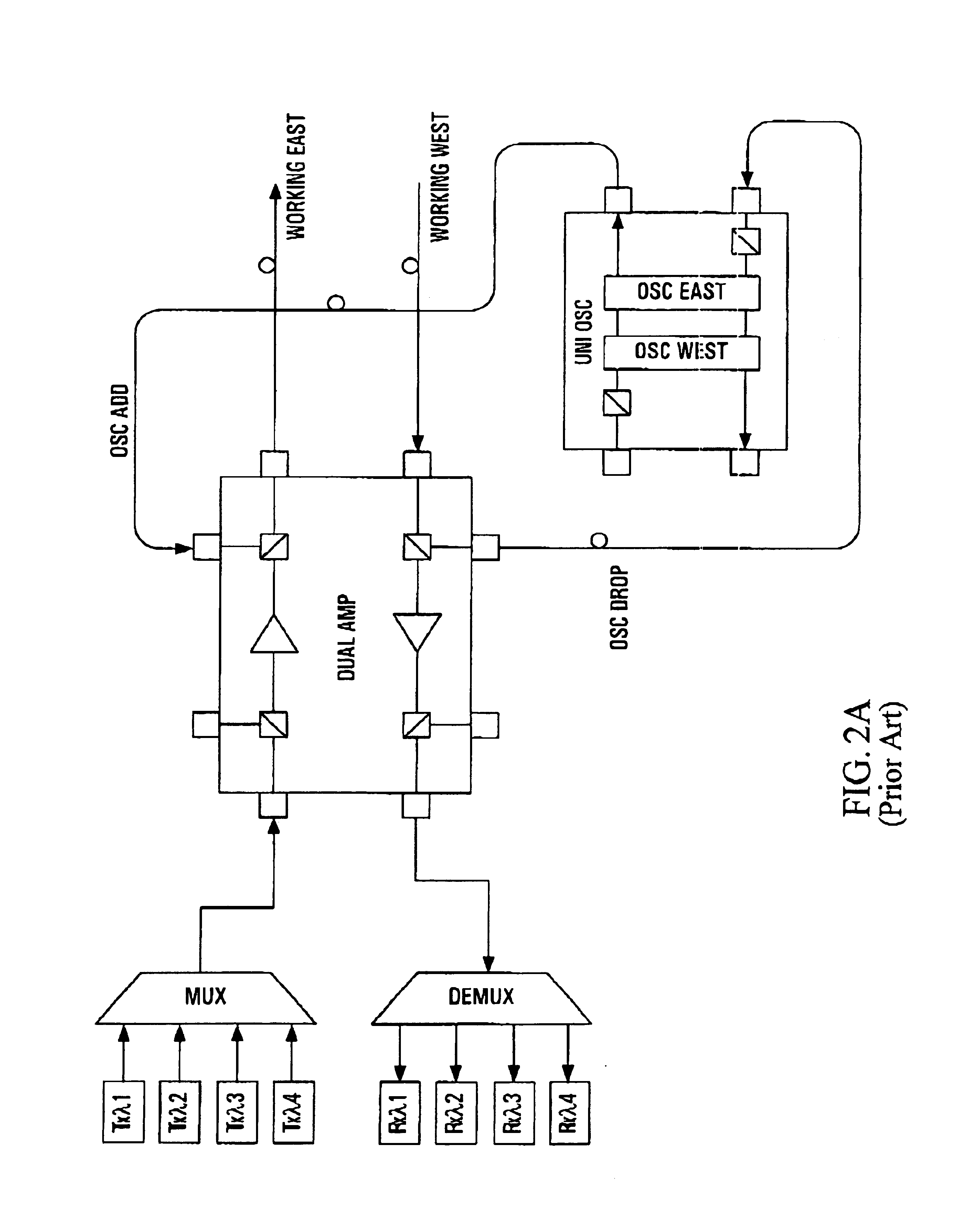
[0032]The present invention is desirable between all interconnected devices in an optical system. For example, a portion of an optical system employing optical amplifier products is shown in FIG. 4. This is simply a high-level block representation of FIG. 2a, the typical arrangement at a line terminating equipment (LTE) site. Note that unidirectional tra...


PUM


Abstract

To automate fiber connectivity management in optical systems, a dedicated low bit-rate communications channel unique to each fiber connection in an optical system is provided. The dedicated communications channel simplifies fiber connectivity management by supporting the exchange of port identification information from one optical component to another after which processing determines if the specific connection is a desired association. The dedicated communications channel supports optical interconnection surveillance for all card-to-card optical connections within a group of related cards or within an optical network link. Automating fiber connectivity management in this manner will enhance future products by simplifying the fiber connection validation process and ensuring that any specific connection between optical components is the required association. This will be particularly useful in complex optical environments with many interconnected devices and where troubleshooting faulty connections would be time-consuming and, therefore, very costly.

Description

FIELD OF THE INVENTION[0001]This invention relates to optical connectivity management and, more particularly, to a method and apparatus for verifying optical connections in an optical system.BACKGROUND OF THE INVENTION[0002]The demand for increased network capacity brought on largely by the advent of the information age has led to the introduction of high bit rate optical links employing a technology known as dense wavelength division multiplexing (DWDM). Carriers are always looking to maximize their network capacity and multiplex as many wavelength channels as possible onto a single optical fiber.[0003]In the future, bandwidth-hungry carriers will continue to demand increased transport capabilities to handle the explosion in the volume of digital traffic. At the transport level, this will likely be accommodated through the use of DWDM with 100 or more wavelengths on a single optical fiber, and with each wavelength carrying a high bit rate channel. If a large number of such multi-wa...

Claims


Application Information

Patent Timeline
IPC IPC(8): H04B10/08G01M11/00H04B10/07H04B10/077H04B10/25H04B10/2581
CPCH04B10/0771H04B10/0775H04B2210/071
Inventor HINDS, MARK R.ST. LAURANT, STEPHANE
Owner CIENA
Why Eureka
Try Eureka