
System and method for remote optical digital networking of computing devices

a computing device and optical digital networking technology, applied in the field of hand-held electronic devices, can solve the problems of inconvenient public setting of wired connection, high cost of radio frequency modems, inconvenient travel, etc., and achieve the effect of wide distribution and increase of rang

Inactive Publication Date: 2005-07-19
GLOBALFOUNDRIES US INC
View PDF5 Cites 233 Cited by
  • Summary
  • Abstract
  • Description
  • Claims
  • Application Information

AI Technical Summary

Benefits of technology

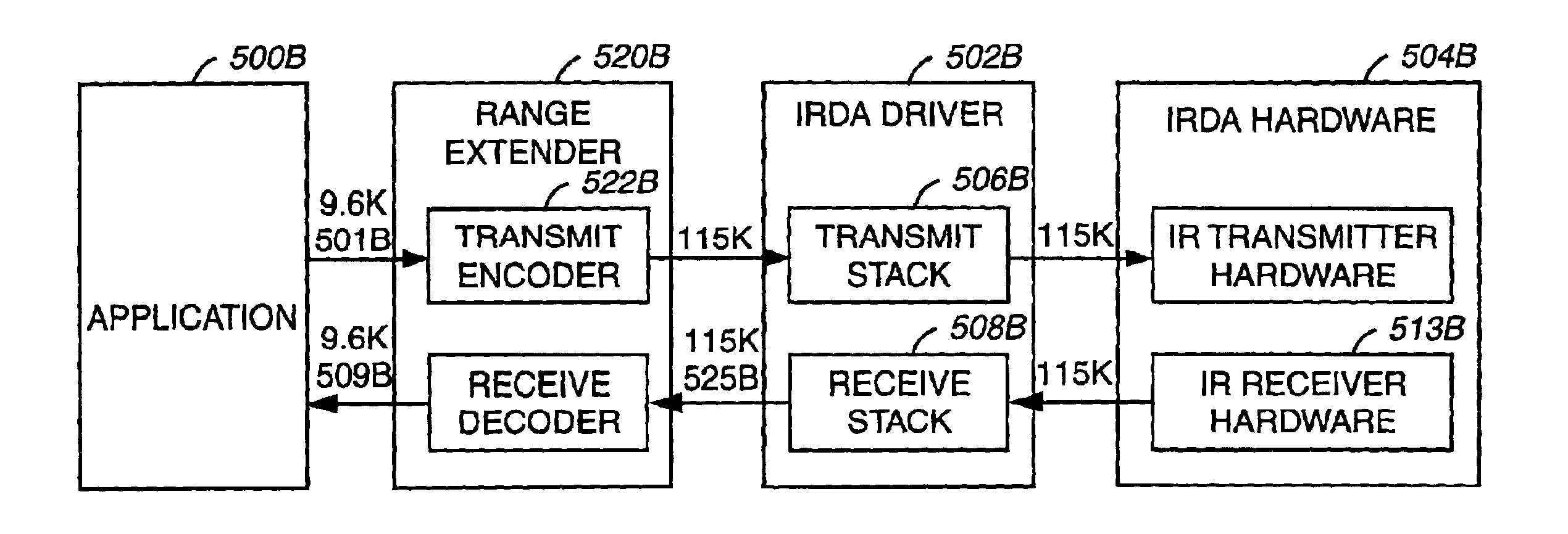
[0012]The invention increases current IRDA ranges from 1 m to 10 meters or more. The range increase can be accomplished by changing the software that controls the IRDA hardware without modifying the IRDA hardware. The software (code) can be changed at the factory by the manufacturer or in the field by the user, typically by uploading a driver that controls the IRDA hardware. It is possible to distribute the code over the Internet, allowing wide distribution of the invention to many users.
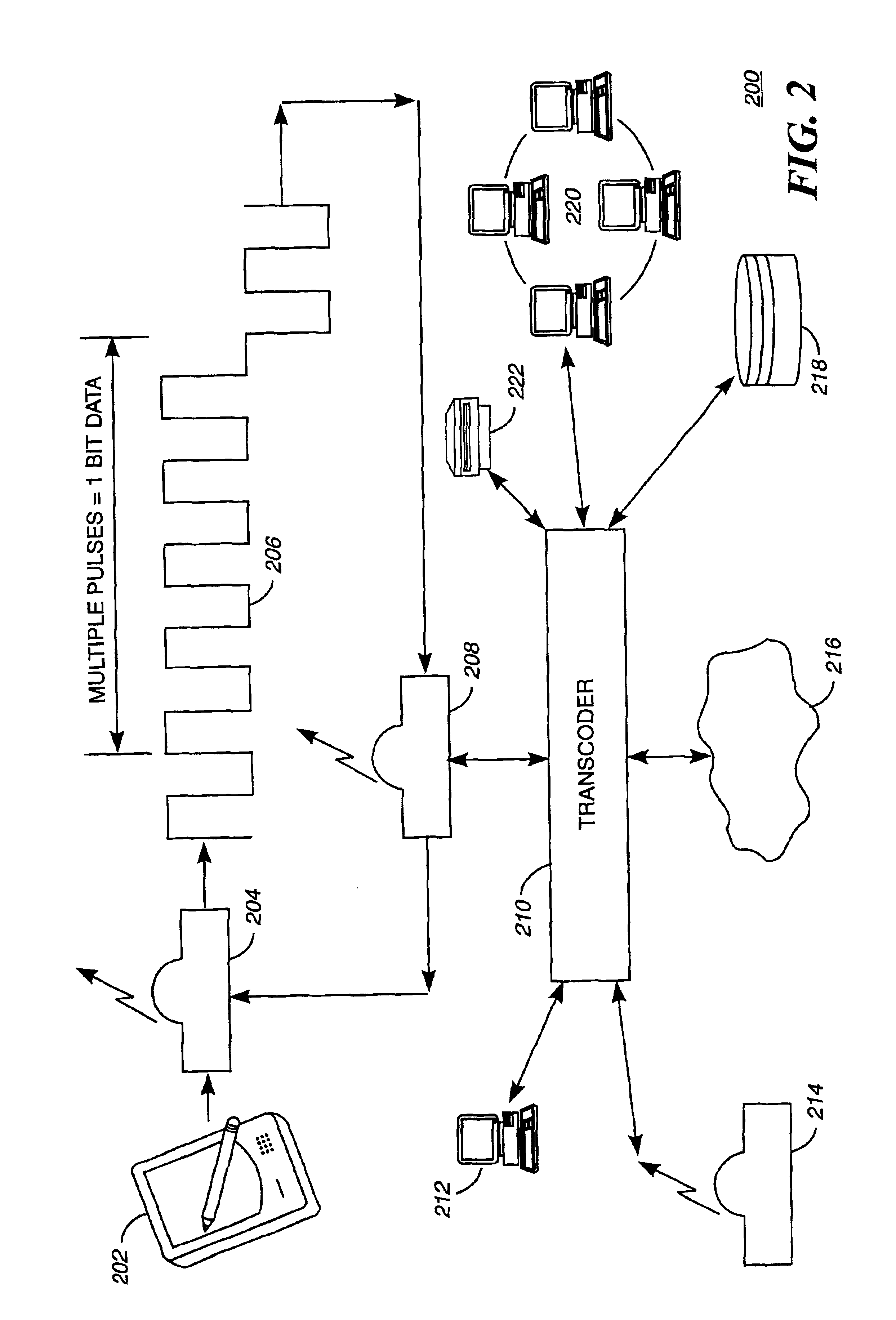
[0013]The base stations can also serve the function of relay stations, allowing two or more optical devices to communicate over great distances. In addition, transcoder features of the invention allow heterogeneous devices and programs to communicate with each other.

Problems solved by technology

This transfer, however, has involved compromise.
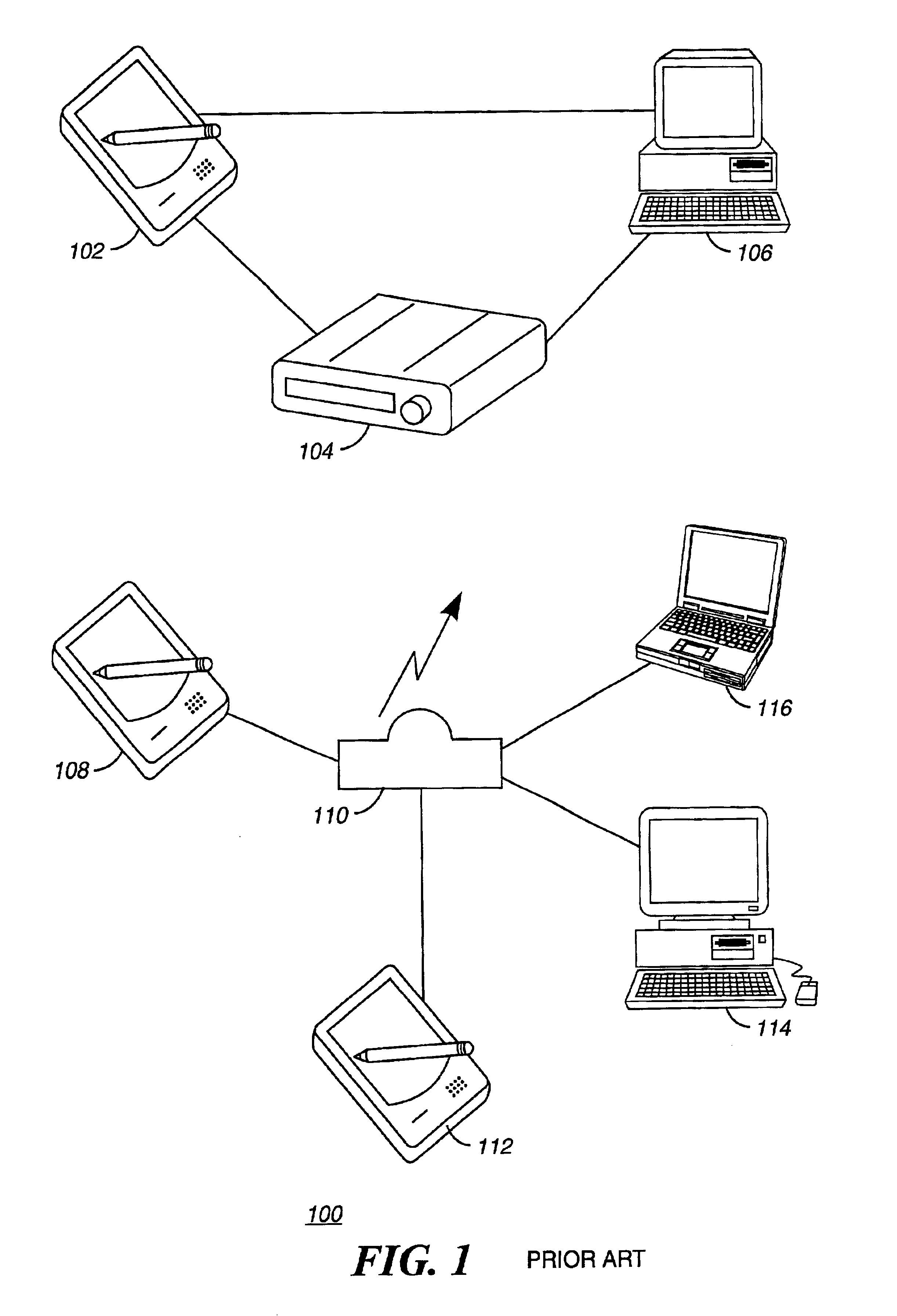
Further, wired connection is inconvenient in public settings (restaurants, retail stores), travel (airports, train stations) and in vehicles (airplanes, cars, buses, trains).
Radio frequency modems are expensive, often not allowed to operate in airplanes and hospitals, and are regulated by laws that vary by country.
IRDA also does not teach multicast communication between a plurality of devices.
In addition, the optical protocols are application and device specific, making it difficult to communicate between heterogeneous devices and applications.

Method used


Image

  • System and method for remote optical digital networking of computing devices
  • System and method for remote optical digital networking of computing devices
  • System and method for remote optical digital networking of computing devices

Examples


Embodiment Construction

[0024]It is important to note that these embodiments are only examples of the many advantageous uses of the innovative teachings herein. In general, statements made in the specification of the present application do not necessarily limit any of the various claimed inventions. Moreover, some statements may apply to some inventive features but not to others. In general, unless otherwise indicated, singular elements may be in the plural and vice versa with no loss of generality.

[0025]In the drawing like numerals refer to like parts through several views.

Remote Optical Digital Networking of Computing Devices

[0026]FIG. 2 is a block diagram (200) of the basic structure for Remote Optical Digital Networking of Computing Devices as practiced by this invention. The Remote Optical Digital Networking of computing devices comprises a PDA (202), an optical transceiver (204) built into the PDA, an access point (208) and a transcoder (210) that permits communication with a plurality of diverse dev...


PUM


Abstract

This invention extends the range of optical data of mobile device by trading speed for distance as well as integrating a plurality of pulses over time to define a single bit of information. The present invention uses a number of integrated pulses to represent a single bit instead of utilizing a one to one correspondence between pulses and bits. The present invention executes a range extender application which executes on the mobile device without any hardware modification to the mobile device. The range extender application causes the optical transmitter to “stutter” or repetitively emanate the identical pulse representing a bit of information. Sufficient photons are thereby gathered at a receiver to reach a predetermined threshold. A tradeoff of the data transmission frequency in this invention is that a signal intensity drops by a factor of 100 when distance increases by a factor of 10 yielding a distance / intensity ratio of {fraction (1 / 10)}.

Description

CROSS-REFERENCE TO RELATED APPLICATIONS[0001]Not ApplicableBACKGROUND OF THE INVENTION[0002]1. Field of the Invention[0003]The present invention relates generally to hand-held electronic devices. More specifically the present invention relates to a communications technique for facilitating data transfer between a hand-held device and a station.[0004]2. The Prior Art[0005]Prior art related to the invention that is currently on the market comprises the software aspect of networking and resource discovery. For example, International Business Machine's TSpaces is an attempt to provide developers with a Java-based distributed-object architecture including a development platform, processing environment, and addressing mechanism. Also, WBI, or Web Intermediaries, addresses the concept of transcoding. WBI intermediaries are computational entities that can be positioned anywhere along the HTTP stream and are programmed to tailor, customize, personalize, or otherwise enhance data as they flow...

Claims


Application Information

Patent Timeline
IPC IPC(8): H04L1/08H04B10/10
CPCH04B10/1149H04L1/08H04B10/00H04B10/114
Inventor ZIMMERMAN, THOMAS G.
Owner GLOBALFOUNDRIES US INC
Learn More