Visual position indicator for valves with linear moving valve stem

a technology of linear moving valve and visual indicator, which is applied in the direction of functional valve types, water mains, gas/liquid distribution and storage, etc., can solve the problems of difficult to determine at a glance whether a valve is open or closed, serious injury, and known types of indicating devices are generally not well suited for use, so as to facilitate manufacturing and enhance the safety of manual valves

Inactive Publication Date: 2005-07-26
TORRENT TRADING
View PDF19 Cites 23 Cited by
  • Summary
  • Abstract
  • Description
  • Claims
  • Application Information

AI Technical Summary

Benefits of technology

[0014]It is an additional object of the present invention to provide an inexpensive means to provide a visual valve position indication.
[0015]It is another object of the present invention to provide visual position indicating means

Problems solved by technology

It is often difficult to determine at a glance whether a valve is open or closed.
This problem is of particular concern in consumer goods, such as with valves on propane gas tanks, where harmful gases could escape without notice and potentially cause serious injury.
Known types of indicating devises are generally not well suited for use in valve-containing consumer goods because these

Method used


Image

  • Visual position indicator for valves with linear moving valve stem
  • Visual position indicator for valves with linear moving valve stem
  • Visual position indicator for valves with linear moving valve stem

Examples


Embodiment Construction

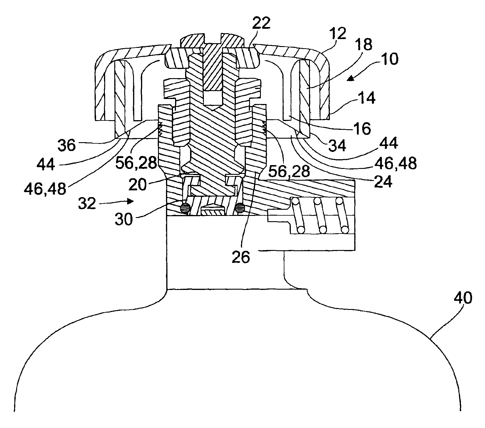
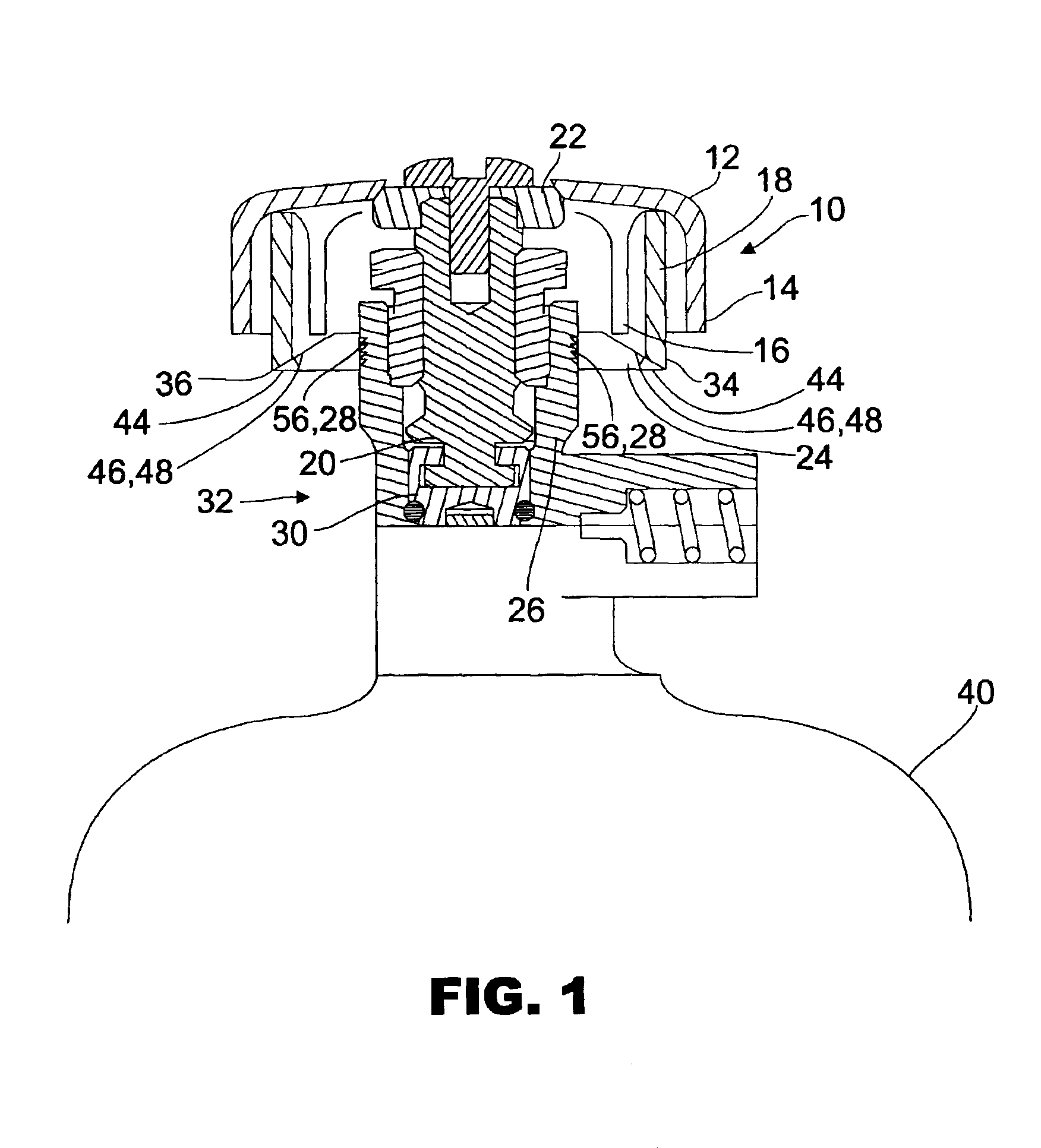
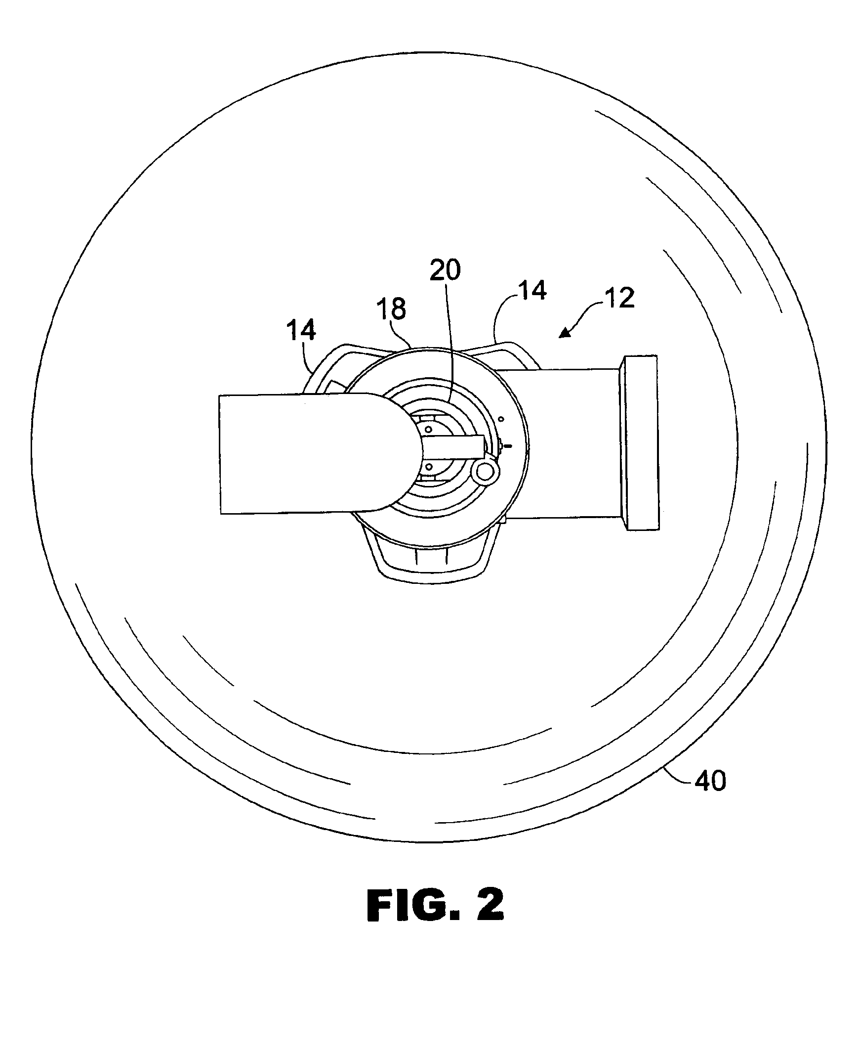
[0024]Referring now to the cross-sectional view in FIG. 1, there is illustrated hand wheel assembly 10 comprised of an exterior hand grip 12 with peripheral sidewalls 14 forming a recessed cavity 16 on the underside of grip 12. Sidewalls 14 are preferably provided with a surface and shape suitable for secure manual gripping. Disposed within cavity 16 is an integral downward depending annular sleeve 18.

[0025]Hand wheel assembly 10 is attached to a valve stem 20 by a fastener 22. A grommet 24 is attached to the upper portion of a valve bonnet 26. Grommet 24 may be affixed by any number of means, although preferably by an interference fit. Grommet 24 may be of a brightly contrasting color for enhanced visibility, or of a neutral or metallic color, so long as it is visible to the operator. A groove 28 may be precisely machined or otherwise formed in valve bonnet 26 corresponding to the limit of travel of stem 20.

[0026]In the preferred embodiment, stem 20 is threadedly engaged with a val...


PUM


Abstract

The present invention relates to a visual valve indicator comprised of a handle assembly with peripheral sidewalls attached to a linear moving valve stem for opening and closing of the valve and a grommet stratified into one or more color bands attached to and surrounding the base of the valve stem. A breakaway portion of the grommet allows the handle assembly to close if the grommet is frozen, by breaking away from the grommet. A sawtooth-edged inner radius of the grommet allows the grommet to slide one direction when pushed down by the handle assembly, if the valve is worn.

Description

RELATED APPLICATION[0001]This is a continuation-in-part of patent application Ser. No. 10 / 016,227, filed Oct. 31, 2001, now U.S. Pat. No. 6,655,316.FIELD OF THE INVENTION[0002]The present invention relates to an apparatus for visually indicating the open and closed position of a valve having a linear moving valve stem.BACKGROUND OF THE INVENTION[0003]It is often difficult to determine at a glance whether a valve is open or closed. This problem is of particular concern in consumer goods, such as with valves on propane gas tanks, where harmful gases could escape without notice and potentially cause serious injury. Known types of indicating devises are generally not well suited for use in valve-containing consumer goods because these indicators are typically integrated with the valve assembly and / or contain a number of moving parts which increase the possibility of malfunction and also increase the cost of production.[0004]Known inventions include those in which the valve indicator is ...

Claims


Application Information

Patent Timeline
IPC IPC(8): F16K17/04F16K37/00
CPCF16K17/0413F16K37/0008Y10T137/8225
Inventor KERGER, LEONPISTOR, BERT
Owner TORRENT TRADING
Why Eureka
Try Eureka