
Device for separating solids from liquids by means of flotation

a technology of solids and liquids, applied in wet separation, machine/engine, textiles and paper, etc., can solve the problems of reduced operating reliability, scattered propulsion jets, low overall gas loading, etc., and achieves favourable placement, avoiding short circuit flows, and good overall flow patterns

Inactive Publication Date: 2005-07-26
ANDRITZ AG
View PDF14 Cites 9 Cited by
  • Summary
  • Abstract
  • Description
  • Claims
  • Application Information

AI Technical Summary

Benefits of technology

[0008]The inventive concept is directed to several, e.g., at least three, individual injectors being arranged in one row. This provides efficient and easy gas access, which is present to the same extent for each individual nozzle. This concept applies to all injectors or nozzles regardless of the number of suction points.
[0010]The invention permits a very favourable placement of the injectors within the flotation cell, distributed over the surface area, and thus a better overall flow pattern.
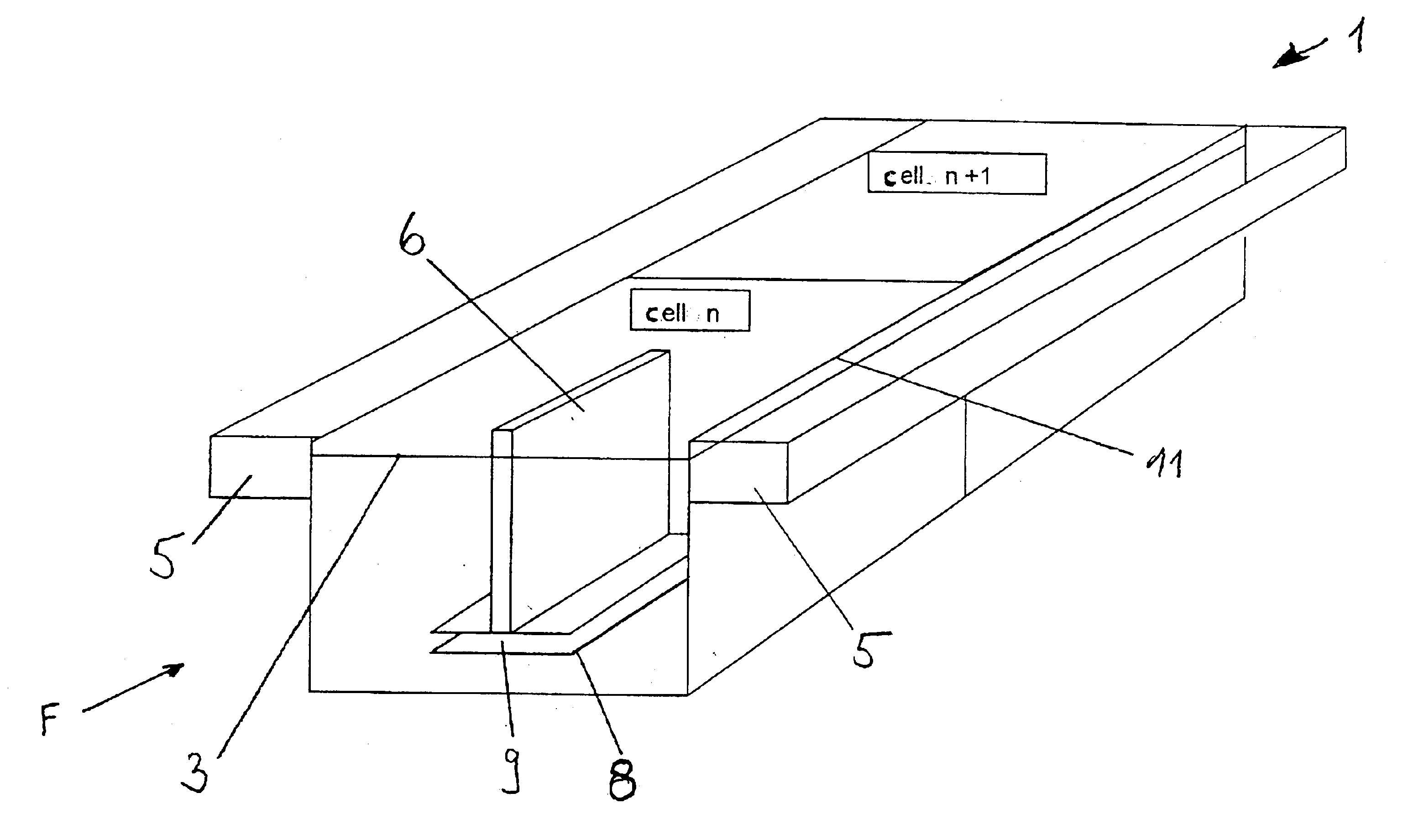
[0011]In an advantageous embodiment the rows are arranged in axial direction in the flotation cell. As a result, this achieves an even flow of foam over the entire cell length in the direction of the overflow weir. Furthermore, the accept or pulp to be aerated again can be removed by suction while largely avoiding short circuit flows.
[0012]In a flotation cell with a foam channel, the injector rows are arranged on the side of the flotation cell opposite the foam channel, which ensures complete flow through the entire flotation cell.
[0013]It has proved particularly advantageous if the injector rows are arranged in the middle of the flotation cell if there are two foam channels. This guarantees even loading of the overflow weirs and foam channels.

Problems solved by technology

Nevertheless, two disadvantages arise when using this process in large-scale industrial applications:
As a result of this short supply, there is a lower overall gas loading, which can lead to the propulsion jet being scattered.
This reduces the operating reliability and / or the desired distribution of bubble sizes widens, which leads to a drop in efficiency in selective flotation or to higher losses.

Method used


Image

  • Device for separating solids from liquids by means of flotation
  • Device for separating solids from liquids by means of flotation
  • Device for separating solids from liquids by means of flotation

Examples


Embodiment Construction

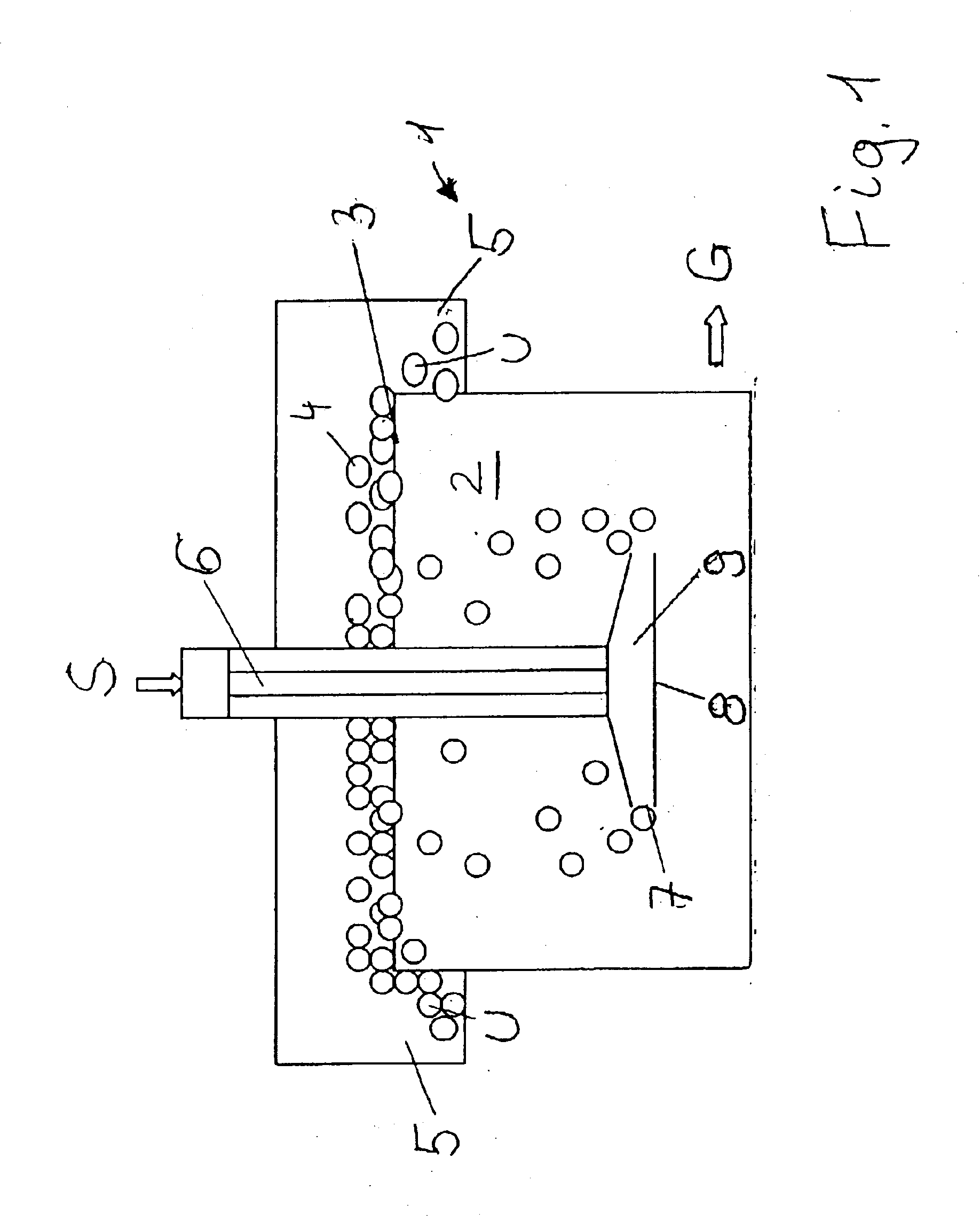
[0020]FIG. 1 shows a diagram of a flotation unit in which the device according to the invention is installed. The flotation cell 1 is filled for the most part with suspension 2, on the surface 3 of which a layer of foam 4 forms, containing as large a portion as possible of the impurities and ink particles to be removed by flotation. The foam 4 can drain off through a foam channel 5 as overflow U. The fibre stock suspension S enters cell 1 through the nozzle unit (injector bundle) 6 and is discharged through diffuser 9. The dispersion of bubbles and fibre stock leaves the diffuser 9 after impinging on an impact plate 8. The bubbles adhere to the hydrophobic impurities and carry them to the surface 3. The cleaned suspension leaves the flotation cell as accept G.

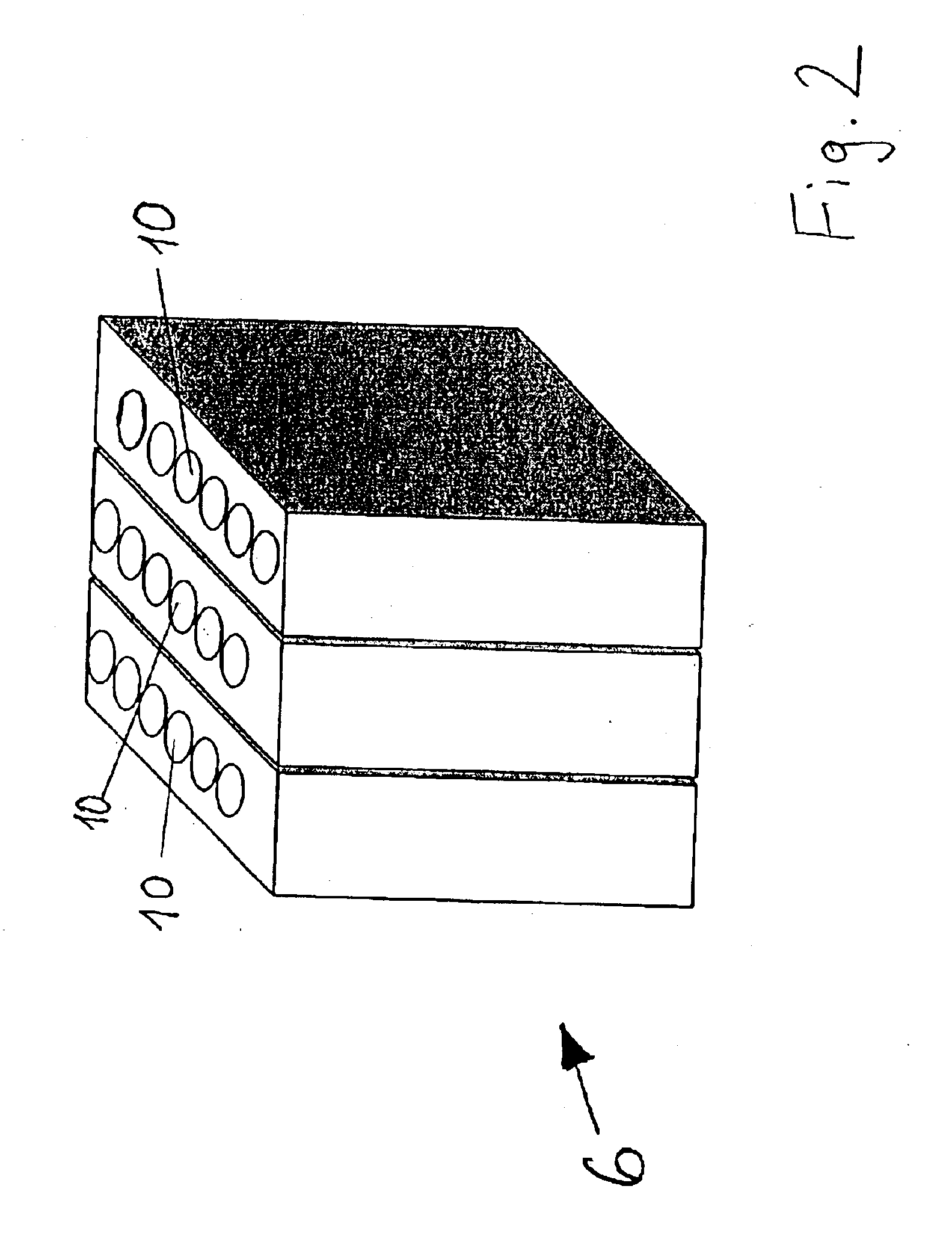
[0021]In FIG. 2 a diagram illustrates a possible variant of a line injector bundle 6 according to the invention, each with six individual injectors 10. In this case, the number of injectors can be varied and the requirements ad...


PUM

PropertyMeasurementUnit
oblique angleaaaaaaaaaa
sizesaaaaaaaaaa
Hydrophobicaaaaaaaaaa

Abstract

The invention relates to a device for separating solids from liquids by means of flotation, particularly for separating impurities and ink particles from fibre suspensions, with several injectors 10, which are provided inside a flotation cell 1. It is mainly characterised by the injectors 10 being arranged in one row.

Description

BACKGROUND OF THE INVENTION[0001]The invention relates to a device for separating solids from liquids by means of flotation, particularly for separating impurities and ink particles from fibre suspensions, with several injectors, which are provided inside a flotation cell.[0002]Deinking flotation is a mechanical process for separating impurities and ink particles from fibre suspensions, particularly those produced in waste paper treatment. This process is linked to generating a suitable amount of gas bubbles over an appropriate range of bubble sizes. By changing the gas-liquid flows and the distribution of bubble sizes, ores, etc. can also be separated from low-grade, unusable material. A similar principle is applied in solid-liquid separation, e.g. in waste water.[0003]Hydrophobic solids or such solids as ink particles or stickies (e.g. also coal as accept material) that have been made hydrophobic by applying surface-active substances are carried to the surface of the liquid by the...

Claims


Application Information

Patent Timeline
Patent Type & Authority Patents(United States)
IPC IPC(8): D21B1/00D21B1/32D21F1/66D21F1/70
CPCD21B1/327D21F1/70Y10S261/75Y02W30/64
Inventor GABL, HELMUTH
Owner ANDRITZ AG
Learn More