Bi-directional reflectance distribution function determination by large scale field measurement

a large-scale field measurement and bi-directional reflectance technology, applied in the direction of optical radiation measurement, instruments, material analysis, etc., can solve the problems of sample size limitation, sample without loss of original information, and limited usefulness of creep in such applications, so as to improve the camouflage properties of military targets, reduce target-background signature contrast, and facilitate the effect of practicality

Inactive Publication Date: 2005-07-26
THE UNITED STATES OF AMERICA AS REPRESENTED BY THE SECRETARY OF THE NAVY +1
View PDF8 Cites 39 Cited by
  • Summary
  • Abstract
  • Description
  • Claims
  • Application Information

AI Technical Summary

Benefits of technology

[0011]Generally, the inventively obtained BRDF information relates the differential scattered power to the differential incident power. This BRDF information can be used according to this invention to predict target signatures in the viewing geometries of all azimuth and elevation angles under various environmental conditions. The present invention provides for new techniques of target signature evaluation measurement, such as may be of interest to the U.S. Navy, wherein BRDF and background measurements are included. Further possible benefits of inventive practice include the modification of existing paint (e.g., on U.S. Navy ships and vehicles) for reducing target-background signature contrast and spatial variation of the target signature in order to improve the camouflage properties of

Problems solved by technology

However, CREEP is limitedly useful in such applications, since CREEP calculations result only in qualitative answers.
Such reflectometric devices and techniques are limited in terms of size of the sample.
A notable disadvantage of this methodol

Method used


Image

  • Bi-directional reflectance distribution function determination by large scale field measurement
  • Bi-directional reflectance distribution function determination by large scale field measurement
  • Bi-directional reflectance distribution function determination by large scale field measurement

Examples


Embodiment Construction

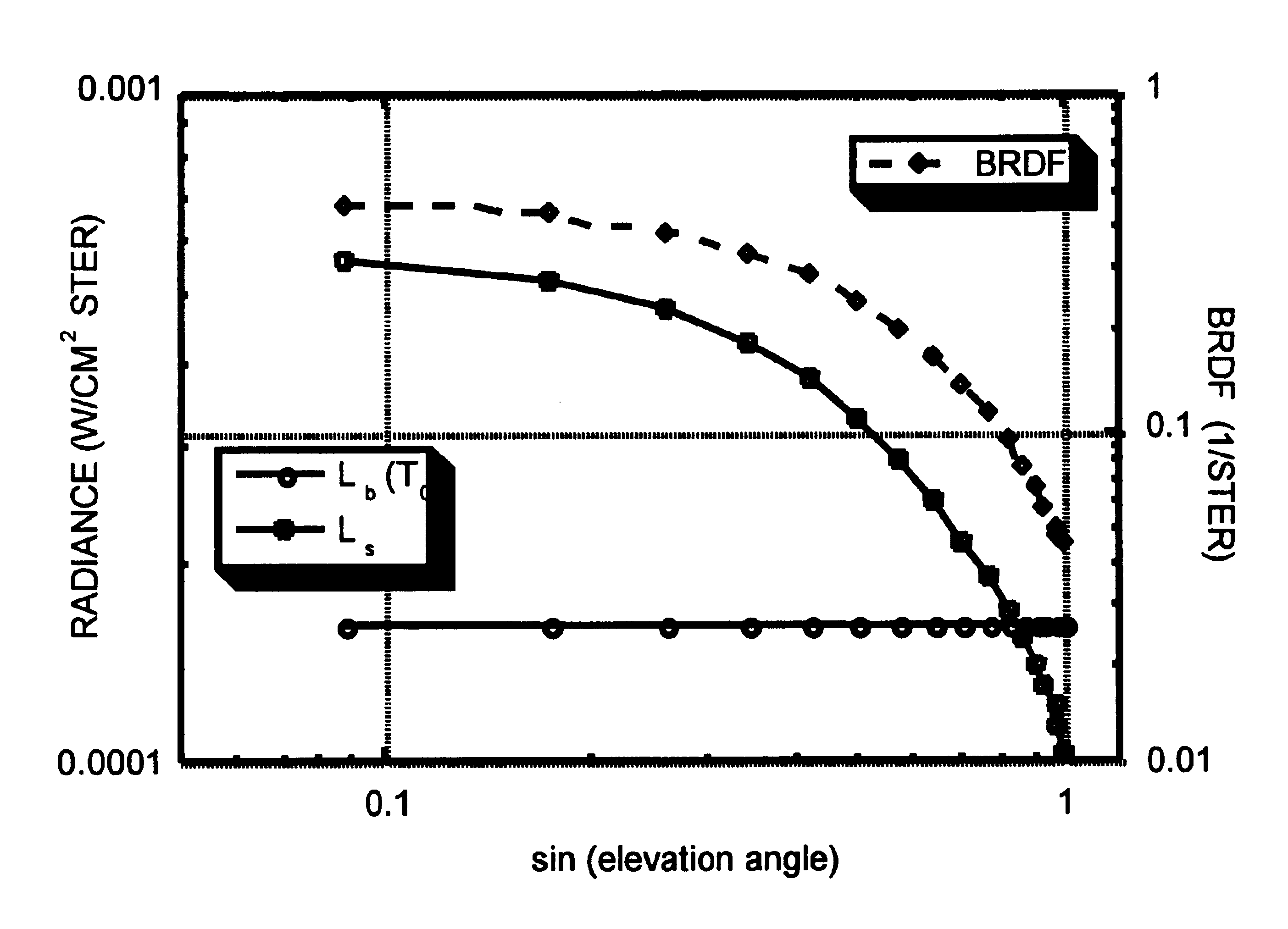
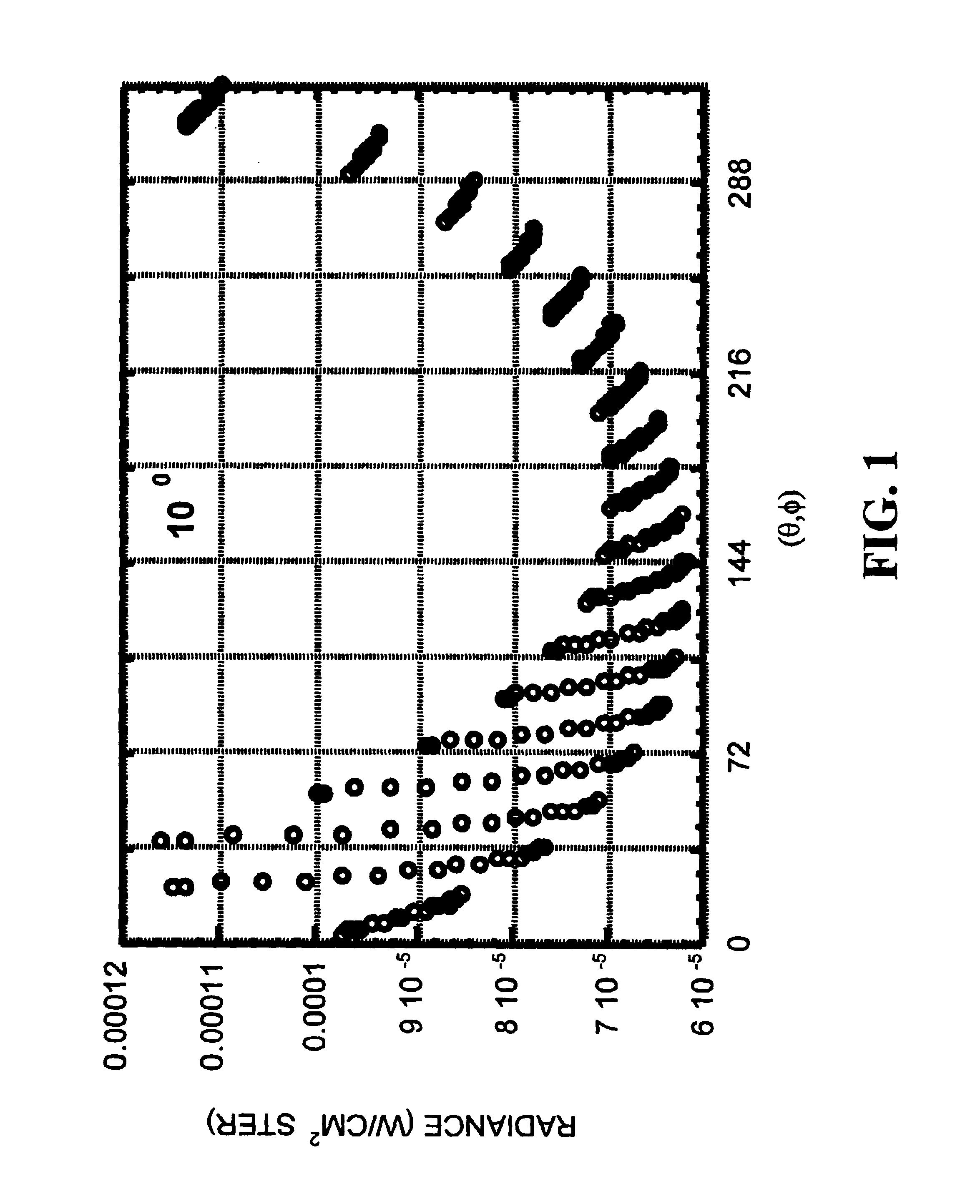
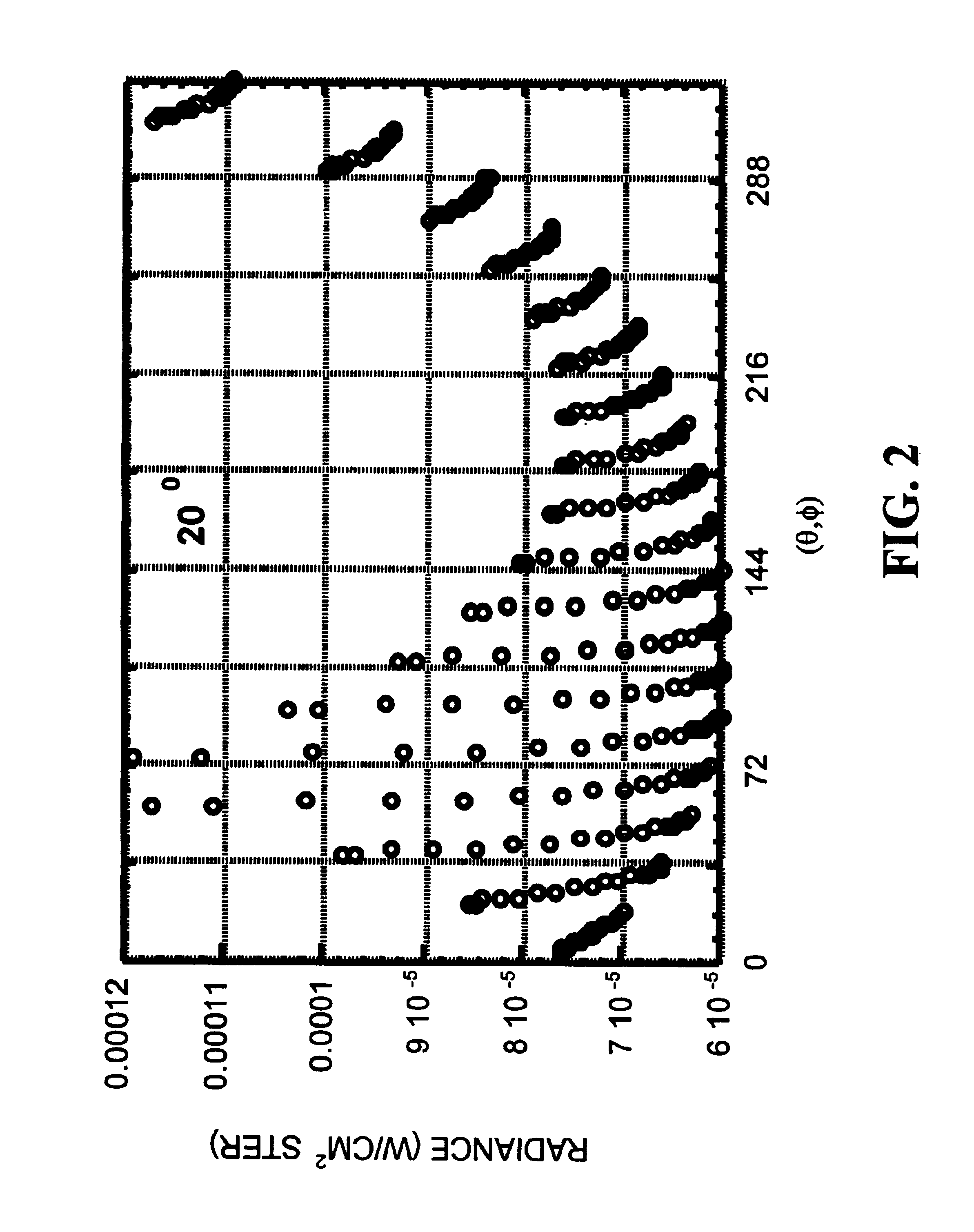
[0018]The energy source of target radiance comes from the thermal emission of the surface itself and partially reflected background of sky / sea / terrain and sun irradiance at the surface. In accordance with typical embodiments of the present invention, the BRDF is calculated numerically by taking properly chosen images of the target and its hemispheric background under (i) different geometrical viewing conditions or (ii) timely changing environmental conditions. Natural background, including the sun, is the source of illumination for the target surface. The recorded images of the target and its associated surrounding background are radiometrically calibrated against the blackbodies to get radiance from pixel values.

[0019]In accordance with the present invention, the BRDF can be determined accurately (with the help of a theoretical model such as developed by NSWCCD) by considering the images of the target surface in the selected / predetermined favorable background conditions. The invent...


PUM


Abstract

Thermal images of an object are produced outdoors so as to be significantly differentiated temporally and/or geometrically and be inclusive of natural background such as would be illuminated by sunlight. A calibration of the thermal imager (e.g., radiometer) against theoretical blackbody radiation is effected using measured incident radiation, resulting in a calculated pixel intensity. A system transfer function calculation of the pixel intensity is effected, resulting in a radiance. A matrix inversion calculation of all of the radiances considered together is effected, resulting in a bi-directional reflectance distribution function (BRDF). Advantageously, the BRDF is determined from the target in a direct but mathematically-enhanced manner, thereby making economic use of natural illumination and obviating the need for modelling, simulating or reconstructing the target.

Description

STATEMENT OF GOVERNMENT INTEREST[0001]The invention described herein may be manufactured and used by or for the Government of the United States of America for governmental purposes without the payment of any royalties thereon or therefor.BACKGROUND OF THE INVENTION[0002]The present invention relates to methods and apparatuses for determining reflectance characteristics of objects, more particularly for determining the bi-directional reflectance distribution function characteristic of a target surface.[0003]The Bi-directional Reflectance Distribution Function (“BRDF”) is defined as the ratio of the differential scattered power to the differential incident power on a surface. BRDF=ⅆLs⁡(θs,ϕs)ⅆEi⁡(θi,ϕi)=Ps / Ω⁢ ⁢A⁢ ⁢cos⁢ ⁢θsPi / A(1)[0004]The BRDF is typically measured using an apparatus which allows the sample to be illuminated with a collimated beam from a range of incident angles. A receiver, subtending a solid angle, can be positioned at a range of scatter directions. Alternatively, t...

Claims


Application Information

Patent Timeline
IPC IPC(8): G01J5/00G01J5/52G01N21/47
CPCG01J5/0003G01J5/522G01N21/47G01J5/53
Inventor CHEN, HSING-CHENG
Owner THE UNITED STATES OF AMERICA AS REPRESENTED BY THE SECRETARY OF THE NAVY
Why Eureka
Try Eureka